
Optical fiber connection protecting box

A technology of optical fiber splicing and protection box, which is applied in the field of optical fiber communication and optical fiber splicing protection box, which can solve the problems of no protection of the fiber core, failure to protect the fiber core, and fiber core breakage, etc., and achieve the effect of stable splicing

Inactive Publication Date: 2012-09-26
CORNING RES & DEV CORP
View PDF2 Cites 0 Cited by
  • Summary
  • Abstract
  • Description
  • Claims
  • Application Information

AI Technical Summary

Problems solved by technology

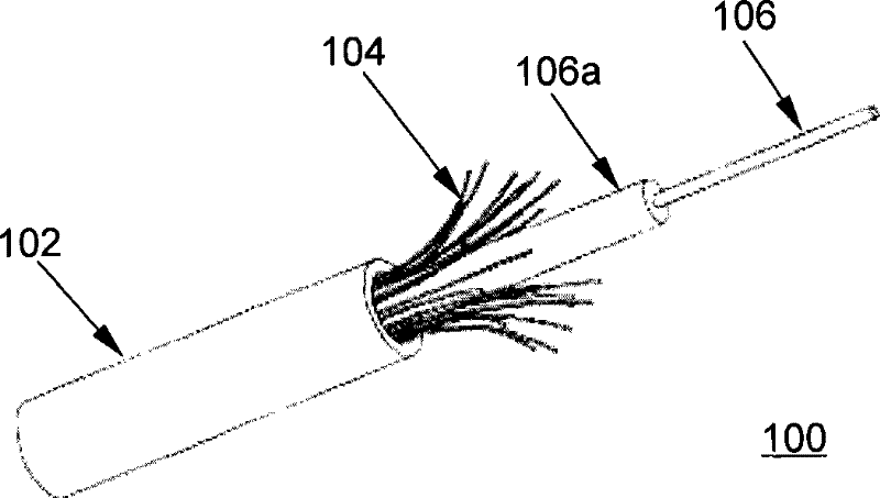
[0004] 1) The entire operation process is relatively long, because it takes time to design, measure, and customize optical cables;
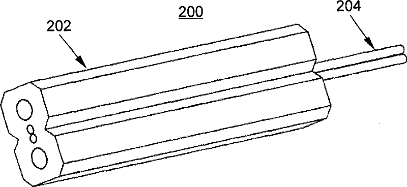
[0005] 2) The location of each customer is uncertain, so it is necessary to repeat the entire process every time it is completed, and customize different optical cables, which is not conducive to inventory management and customer service;
[0006] 3) It is necessary to use optical cables with connectors to pass through the pipes in the building on site, and the optical fibers are easily broken during on-site construction, and the connectors are also easily damaged
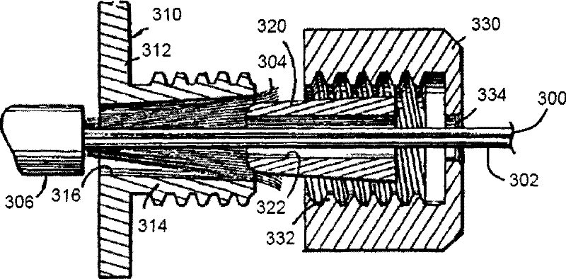
However, the strength member 304 in this fixed structure may move along the axial direction of the fiber and thus cannot protect the fiber core well, and the fiber core 306 may be damaged during such movement
Since the bare fiber splicing device (disclosed as US2006 / 0067637) does not have the effect of protecting the fiber core (bare fiber), when the assembly work is not completed well, it will cause the fiber core (bare fiber) to break and Damage to optical fiber and the entire optical fiber communication line

Method used


Image

  • Optical fiber connection protecting box
  • Optical fiber connection protecting box
  • Optical fiber connection protecting box

Examples


Embodiment Construction

[0041] The technical solutions of the present invention will be further described below in conjunction with the accompanying drawings and embodiments.

[0042] Fiber splicing box

[0043] The present invention mainly provides an optical fiber connection protection box, which is used for connecting ordinary indoor optical fibers and leather optical cables. Refer to Figure 4 as shown, Figure 4 It is a structural diagram of an optical fiber splicing protection box according to an embodiment of the present invention. The optical fiber splicing protection box 400 includes: a base plate 402, at least one pigtail fixing device 404, at least one optical fiber splicing device 406, and at least one leather cable fixing device 408 and lid 412.

[0044] There are a plurality of positioning parts on the base plate 402, the fixing part of the bare fiber splicing device, the fixing part of the pigtail fixing device and the fixing part of the covered cable fixing device, the pigtail fixin...


PUM


Abstract

The present invention discloses an optical fiber connection protecting box for connecting the tail fiber of the common indoor optical fiber and the leather-wire optical fiber. The optical fiber connection protecting box comprises the following components: a substrate which includes a locating part of the tail fiber fixing mechanism and a locating part of the leather-wire optical fiber fixing mechanism which are arranged spacing with each other for a certain distance; a bare fiber connection device which connects the common indoor optical fiber and the bare fiber in the leather-wire optical fiber; a tail wire fixing device which is fixed on the locating part of the tail fiber fixing mechanism of the substrate and connects the tail fiber in the common indoor optical fiber, wherein the bare fiber of the tail fiber traverses the tail fiber fixing device with a prearranged length and the bare fiber connecting device executes connection; and a leather-wire fixing mechanism which is fixed onthe locating part of the skin-wire optical fiber fixing mechanism of the substrate and is connected with the leather-wire optical fiber, and the bare fiber of the leather-wire optical fiber traversesthe leather-wire optical fiber fixing mechanism with a prearranged length and the bare fiber connecting mechanism executes the connection to the bare fiber of the tail fiber. The invention can effectively connect the leather-wire optical fiber with the tail fiber of the common indoor optical fiber and directly fixes the tail fiber through a reinforcing piece in the tail fiber. The leather-wire optical fiber and the tail fiber can be firmly and stably connected, and the fiber core wherein can be effectively protected.

Description

technical field [0001] The present invention relates to optical fiber communication technology, and more specifically relates to an optical fiber connection protection box, especially an optical fiber connection protection box for connecting common indoor optical fiber pigtails and leather cables. Background technique [0002] In a commercial building, a telecommunications room is usually provided as a transit mechanism for users in the building to connect to the telecommunications company's network. When a business customer applies to a telecommunications company to rent an optical fiber to provide broadband access, the telecommunications company usually needs to physically connect the optical fiber connected to the central office in the telecommunications room of the commercial building to the optical port of the business customer's equipment. Usually, the connection between the telecommunications room and the optical port of personal or business customer equipment is real...

Claims


Application Information

Patent Timeline
Patent Type & Authority Patents(China)
IPC IPC(8): G02B6/38G02B6/36
CPCG02B6/4471G02B6/255G02B6/3806G02B6/4477G02B6/2558
Inventor 徐志勇胡贯朋彭裴乐崔一峰鲁斌李德海周俊生
Owner CORNING RES & DEV CORP
Learn More