Cable connector for directly connecting cables by way of piercing cable insulation

A cable connector and cable insulation technology, which is applied in the direction of needle point/slotted plate contact, clamping/spring connection, etc. used to penetrate the insulation wire/cable core wire, and can solve the problem of not being able to adapt to the hardness of the cable insulation layer one by one Changes, poor environmental resistance, large connection pressure dispersion, etc., to achieve the effect of excellent long-term current-carrying performance, excellent environmental resistance, and effective electrical connection

Inactive Publication Date: 2010-10-27
王刚
View PDF0 Cites 9 Cited by
  • Summary
  • Abstract
  • Description
  • Claims
  • Application Information

AI Technical Summary

Problems solved by technology

[0005] Second, the connection pressure dispersion is too large
[0006] Due to the change of temperature, the hardness of the cable insulation has a wide range of changes. The constant contact pressure control scheme of the torque nut provided by this product cannot adapt to the change of the hardness of the cable insulation layer by sample. If the torque is increased, the installation will damage the wire when the temperature is high. Reduce the torque, the installation will be virtual when the temperature is low
[0007] 3. Poor ability to puncture thick insulation
[0008] Since the larger connection pressure is borne by the plastic material, this product is only suitable for 1KV thin insulated cables, and has obvious incompatibility for 10KV insulated cables with thicker insulation layers.
[0009] 4. The radial shear force is too large
[0010] 5. Poor environmental resistance

Method used


Image

  • Cable connector for directly connecting cables by way of piercing cable insulation
  • Cable connector for directly connecting cables by way of piercing cable insulation
  • Cable connector for directly connecting cables by way of piercing cable insulation

Examples


Embodiment Construction

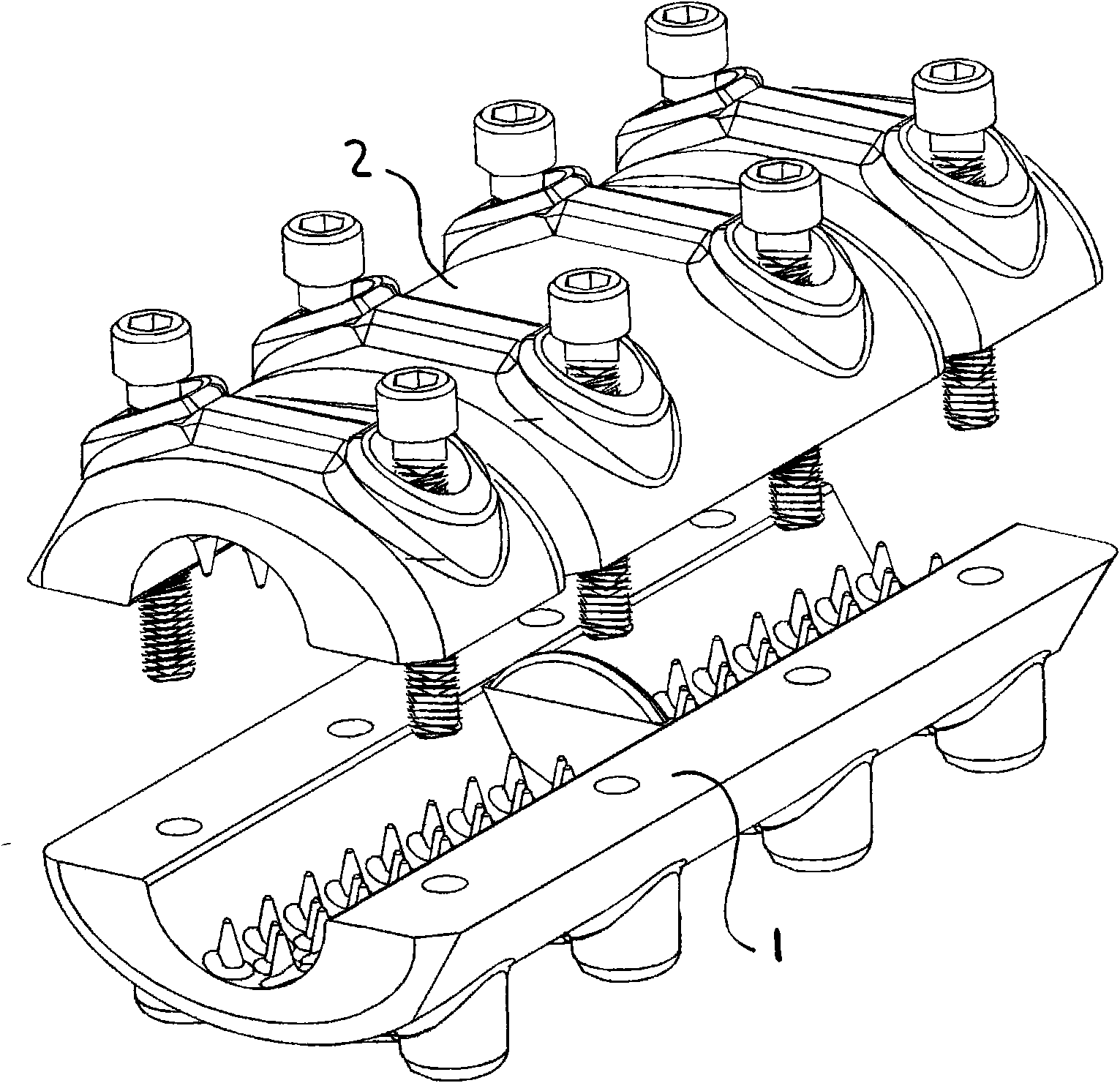
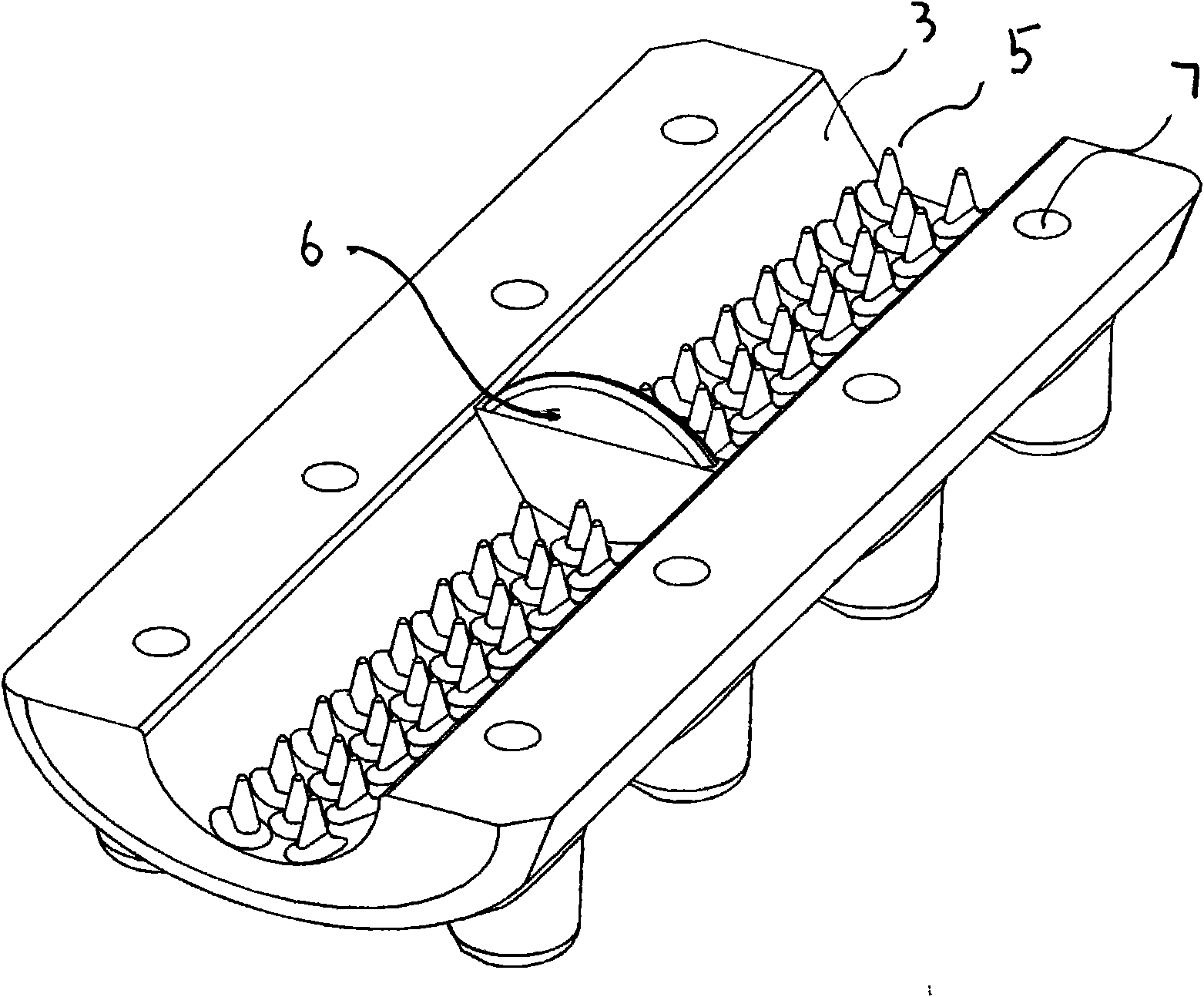
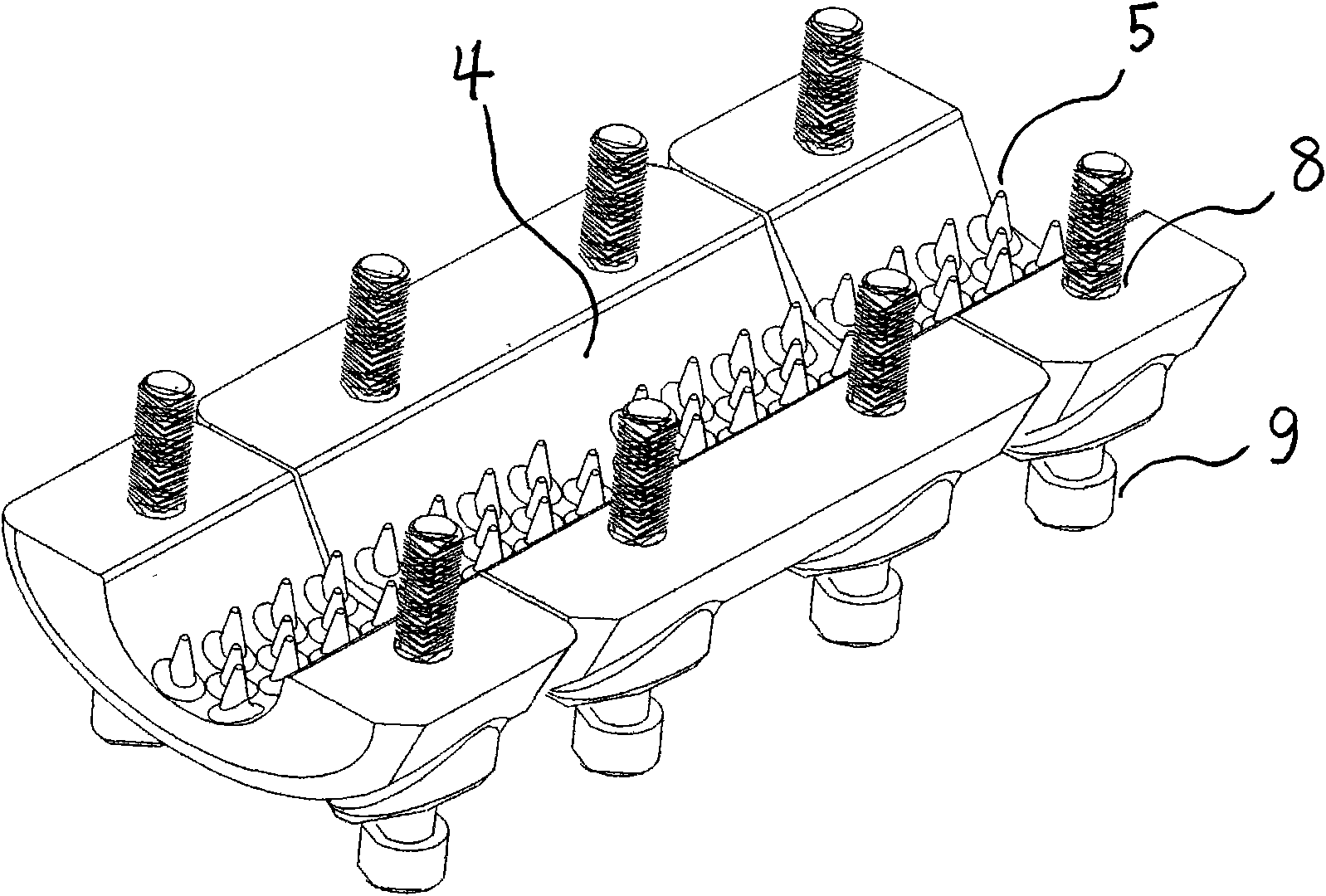
[0019] See Figure 1-5 The specific structure is as follows, the main connector 1, the clamping body 2, the inner arc surface clamped on the main connector body 3, the inner arc surface clamped on the clamp body 4, the conical clamping thorn 5, the upper limit piece of the main connector body 6, the main connection Body screw hole 7, clip solid screw hole 8, connecting bolt 9, protective cover 10.

[0020] When in use, insert the end of the cable with insulation into the clamping inner arc surface 3, 4 on the main connecting body and the clamping body, stop under the stop of the limit piece 6, twist the connecting bolt 9 at the end of the clamping solid slightly, and The end of the cable is fixed with the connector, and then another end of the cable with insulation is inserted into the other end of the clamped inner arc surface 3, 4, and stops under the stop of the limit piece 6, and the solid end of the clamp is connected with a little force Bolt 9, adjust the two cables to ...


PUM


Abstract

The invention discloses a cable connector for directly connecting cables by way of piercing cable insulation, which has an integral aluminum alloy structure produced by casting and comprises a connector main body. The connector main body comprises a main connector, the main connector is provided with a clamped intrados contacted with a cable, and conical clamping piercers which are arranged axially and intensively in a certain radial radian and simultaneously cast with the main connector are arranged on the clamped intrados; the middle part of the clamped intrados of the main connector is provided with limit sheets which are simultaneously cast with the main connector, the main connector is provided with a screw hole and connected with a clamping body by a connecting bolt; the clamping body is provided with a clamped intrados contacted with the cable, and conical clamping piercers which are arranged axially and intensively in a certain radial radian and simultaneously cast with the clamping body are arranged on the clamped intrados. The cable connector of the invention has the advantage that: the electrical connection of the electrical connection part which cannot bear the cable tension is rapidly and effectively completed by piercing the insulation to directly reach a conductor with the conical clamping piercers under the condition that the end insulation of the cable is not stripped.

Description

Technical field: [0001] The invention belongs to the field of electric power stringing fittings, and is a connecting fitting between two tension sections of an outdoor overhead insulated cable or other non-load-bearing electrical connections. Background technique: [0002] In the current construction of electric overhead insulated cable lines, when connecting non-load-bearing jumpers of cables with the same diameter between two tension-resistant sections, the insulation at the ends of the two cables is usually stripped off, and crimped with parallel groove clamps. The gradual oxidation in the air causes the contact resistance of the connection part to gradually increase, and the temperature rise of the contact point gradually increases, which not only increases the line loss, reduces the line operation level, and even burns the cable in severe cases. The wedge-shaped clamp invented in the 1960s has been adopted in many domestic lines. To install the wedge-shaped clamp, the i...

Claims


Application Information

Patent Timeline
Patent Type & Authority Applications(China)
IPC IPC(8): H01R4/24H01R4/46
Inventor 王刚
Owner 王刚
Why Eureka
Try Eureka