Timepiece
A technology of clocks and components, which is applied in the field of clocks and watches with relaxed gear trains, can solve the problems of poor precision, small swing angle of governor, and inability to ensure energy, etc., and achieve the effect of stable precision and extended duration
- Summary
- Abstract
- Description
- Claims
- Application Information
AI Technical Summary
Problems solved by technology
Method used
Image
Examples
no. 1 approach
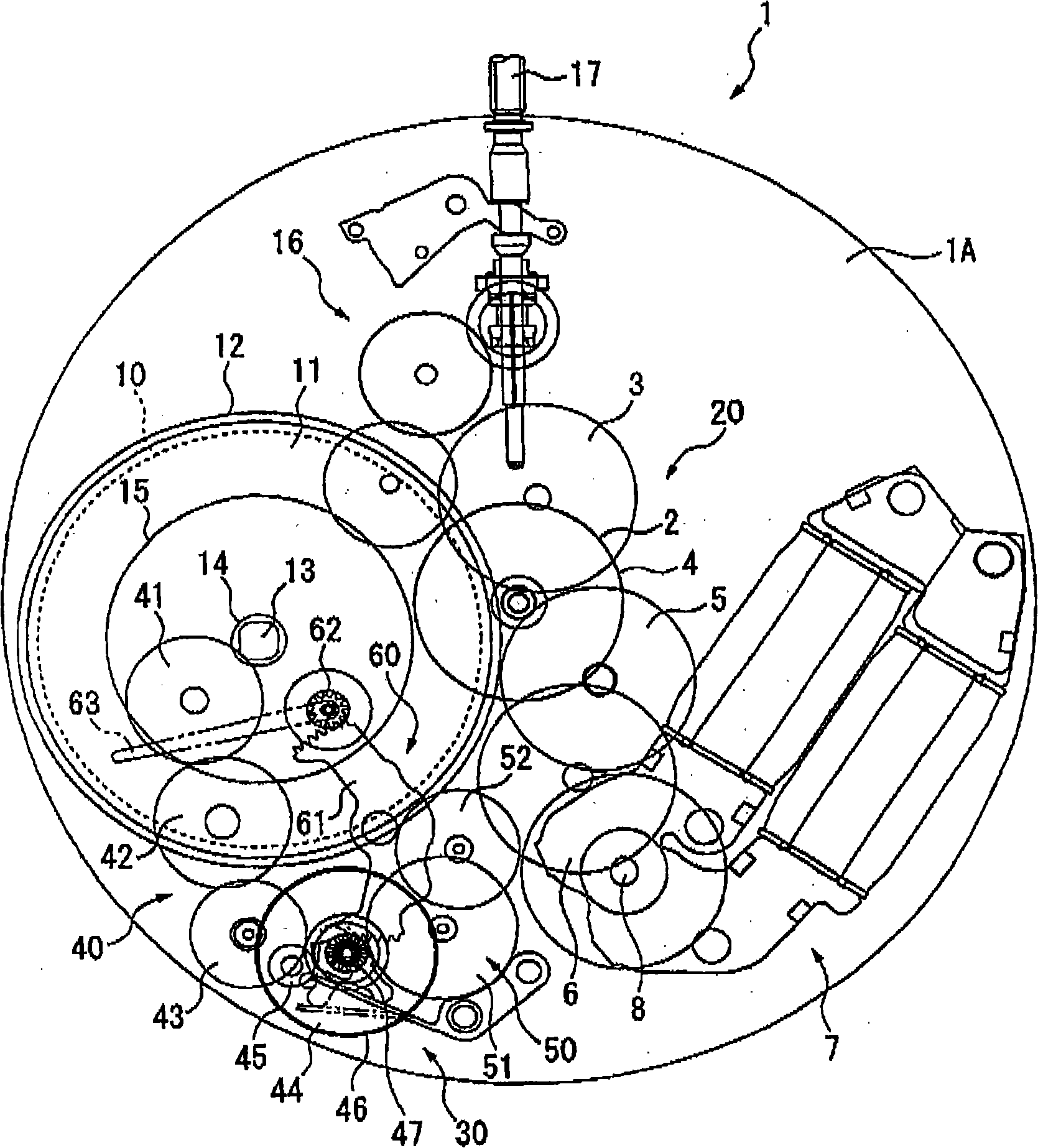
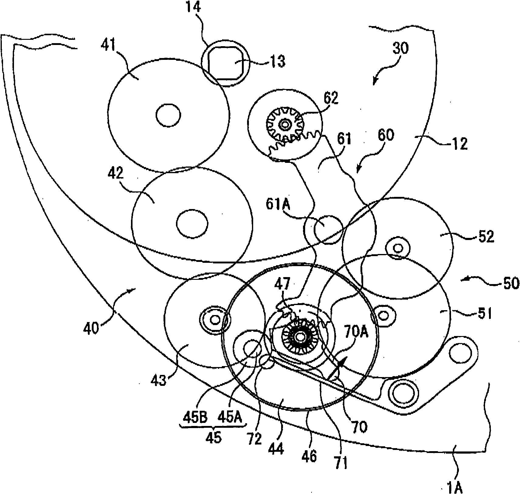
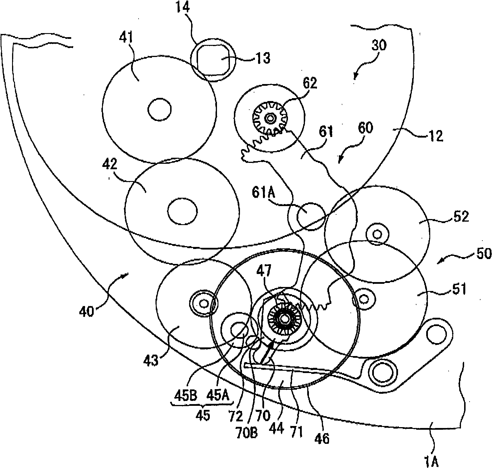
[0048] figure 1 A schematic plan view showing the timepiece 1 according to the first embodiment of the present invention. in the figure 1 Among them, the clock 1 is an electronically controlled mechanical clock, which has: a mainspring 10; a drive train 20 driven by the mechanical energy of the mainspring 10; 30.
[0049] The mainspring 10 is accommodated in a barrel 11, which is configured such that, when the timepiece 1 is a hand-wound timepiece, the outer end of the mainspring 10 is fixed to a barrel gear 12 formed on the outer periphery of the barrel 11, and , when the timepiece 1 is a self-winding timepiece, the outer end of the mainspring 10 abuts against the inner circumference of the barrel 11, and when a torque of more than a predetermined value is added, the movement of the mainspring 10 relative to the barrel 11 Slip inside. In addition, the inner end of the mainspring 10 is fixed on the barrel center shaft 13 provided at the center of the barrel case 11. The ba...
no. 2 approach
[0069] Below, refer to Figure 5 And FIG. 6 explains the second embodiment of the present invention. In this embodiment, the structure of the pressing member which applies torque to a sun gear differs from 1st Embodiment.
[0070] Figure 5 It is a top view showing the main part of the timepiece of this embodiment. The sun lever 80 is fixed to the rotation shaft of the sun gear 87 which is an output wheel in this embodiment.
[0071] The sun rod 80 extends from its rotation center to a position beyond the periphery of the sun gear 87 in a direction intersecting the rotation direction of the sun gear 87 , and rotates in synchronization with the rotation of the sun gear 87 . Here, about Sun Rod 80, at Figure 5 The position indicated by the dashed-two dotted line indicates the sun lever 80 when the mainspring 10 is substantially wound up, and the position indicated by the solid line indicates the sun lever 80 when the mainspring 10 is generally unwound to reach the end of th...
no. 3 approach
[0081] Next, refer to Figure 7 A third embodiment of the present invention is described through FIG. 9 . In the first embodiment, the sun lever is directly pressed by the pressing member (spring member 71 ), but in this embodiment, the pressing member presses the sun lever through another member.
[0082] Figure 7 It is a top view showing the main part of the timepiece of this embodiment.
[0083] The sun rod 80 is provided with a slide member 92 and a guide member 93, the slide member 92 can move linearly along the direction connecting the rotation center side and the outer side of the sun rod 80, and the guide member 93 can move approximately along the direction of the sun rod 80. The slide member 92 is guided in the chord direction of a circle centered on the rotation center of the rod 80 .
[0084] In the guide member 93 , an elongated hole 930 that engages with a protrusion included in the slide member 92 is formed. One end portion 931 of the guide member 93 is pivo...
PUM
 Abstract
Description
Claims
Application Information
 - R&D
- Intellectual Property
- Life Sciences
- Materials
- Tech Scout
- Unparalleled Data Quality
- Higher Quality Content
- 60% Fewer Hallucinations
Browse by: Latest US Patents, China's latest patents, Technical Efficacy Thesaurus, Application Domain, Technology Topic, Popular Technical Reports.
© 2025 PatSnap. All rights reserved.Legal|Privacy policy|Modern Slavery Act Transparency Statement|Sitemap|About US| Contact US: help@patsnap.com


