Yarn-collecting device for compact spinning

A compact spinning and yarn-gathering technology, used in spinning machines, textiles and papermaking, drafting equipment, etc., can solve the problems of consuming airflow, increasing negative pressure, wasting energy, etc., and achieving the effect of saving energy and reducing negative pressure

Inactive Publication Date: 2008-10-08
YUNSHENG HLDG GRP
View PDF1 Cites 7 Cited by
  • Summary
  • Abstract
  • Description
  • Claims
  • Application Information

AI Technical Summary

Problems solved by technology

[0004] There are various devices of this kind, but most of them cannot make the airflow before entering the suction channel exert directional and effective pressure on the whiskers, consume unnecessary airflow above the whiskers, increase the negative pressure, and waste energy

Method used


Image

  • Yarn-collecting device for compact spinning
  • Yarn-collecting device for compact spinning
  • Yarn-collecting device for compact spinning

Examples


Embodiment Construction

[0022] The present invention will be further described in detail below in conjunction with the accompanying drawings and embodiments.

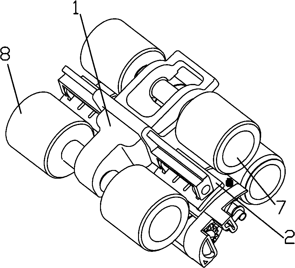
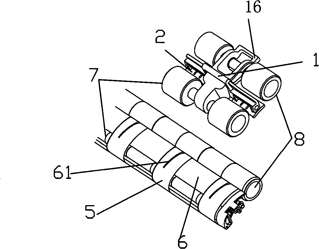
[0023] Such as figure 1 , figure 2 As shown, the yarn-gathering device includes a support 1 and a yarn-gathering air guide 2 arranged between the drafting roller 7 and the gripping roller 8 .

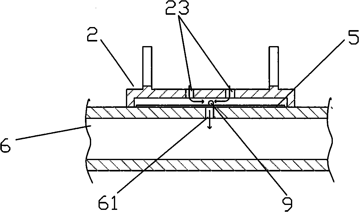
[0024] Such as image 3 As shown, the above-mentioned yarn-gathering air guiding plate 2 is provided with two yarn-gathering air-guiding long holes 23, and the two yarn-gathering air-guiding slots 23 are parallel to each other, and the yarn-gathering air-guiding slots 23 are connected to the suction slots on the accumulation pipe. 61 are parallel and arranged symmetrically on both sides of the suction slot 61.

[0025] A pair of legs 24 are provided on the lower part of the above-mentioned yarn gathering air guide plate 2, straddling the conveyor belt 5 and elastically mounted on the conveyor belt sliding surface 6, the conveyor belt 5 is arranged o...


PUM


Abstract

A yarn accumulation device for compact spinning is arranged between a draft roller and a holding roller, which comprises a yarn accumulation aeroscopic plate and a fixation apparatus. The yarn accumulation aeroscopic plate fixed on a fixation apparatus is provided with two yarn accumulation air long guide holes in parallel each other. The yarn accumulation air long guide holes are in parallel with a pumping seam on an accumulation tube, which are also in a symmetrical arrangement on both sides of the pumping seam. Both ends of the lower part of the polymer yarn air long guide hole are provided with a pair of support legs, spanned a conveyor belt, fit tightly and supported on a sliding surface. The invention has the advantages that the yarn accumulation device is disposed between the draft roller and the holding roller, spanned the conveyor belt and flexibly supported on the sliding surface. Through the guide of the air guide hole on the yarn accumulation aeroscopic plate, the air before entering the pumping channel can be in the implementation of directional effective pressing to the strips. The air above the strips is effectively utilized, thus the negative pressure is reduced and the energy is saved.

Description

technical field [0001] The invention relates to a component for a spinning device, in particular to a yarn gathering device arranged between a spinning drafting device and a twisting device for collecting a fiber strand. Background technique [0002] In the traditional spinning device, the drafted fiber strands are directly connected to the output roller pair of the drafting device for twisting. When twisting, a so-called spinning triangle will appear on the nip line of the output roller pair. Affect the quality of yarn. This is due to the fact that the drawn fiber strands leave the drafting device with a fixed width and are twisted together into a yarn with a smaller diameter. Therefore, in order to eliminate the spinning triangle, the fibers are bundled or compacted in the compaction zone, so that the fiber strands become very thin when they leave the final nip, eliminating the spinning triangle, and the spun yarn It will be more even and firm with less hairiness. [00...

Claims


Application Information

Patent Timeline
Patent Type & Authority Applications(China)
IPC IPC(8): D01H5/72
Inventor 徐时平邬建明王卫
Owner YUNSHENG HLDG GRP
Why Eureka
Try Eureka