
Water tank cleaning machine

A technology for cleaning machines and pools, applied in swimming pools, gymnasiums, buildings, etc., can solve problems such as water flow can not be concentrated, skirts can not be sealed, insufficient negative pressure and water flow, etc., to improve work efficiency, reduce failure rates and maintenance costs Effect

Inactive Publication Date: 2008-10-08
SMARTPOOL
View PDF0 Cites 4 Cited by
  • Summary
  • Abstract
  • Description
  • Claims
  • Application Information

AI Technical Summary

Problems solved by technology

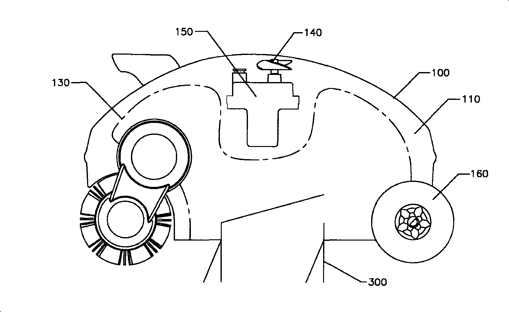
And this kind of skirt still has the danger of being stuck by the uneven bottom of the pool; moreover, this kind of skirt can't be sealed, otherwise the garbage or sediment can't pass through the skirt and be sucked into the cleaning machine, but the skirt without sealing feet, the water flow cannot be concentrated, thus generating insufficient negative pressure and water flow to bring up the garbage or sediment at the bottom of the pool
[0005] In summary, the existing pool cleaners obviously have inconveniences and defects in actual use, so it is necessary to improve them

Method used


Image

  • Water tank cleaning machine
  • Water tank cleaning machine
  • Water tank cleaning machine

Examples


Embodiment Construction

[0027] In order to make the object, technical solution and advantages of the present invention clearer, the present invention will be further described in detail below in conjunction with the accompanying drawings and embodiments. It should be understood that the specific embodiments described here are only used to explain the present invention, not to limit the present invention.

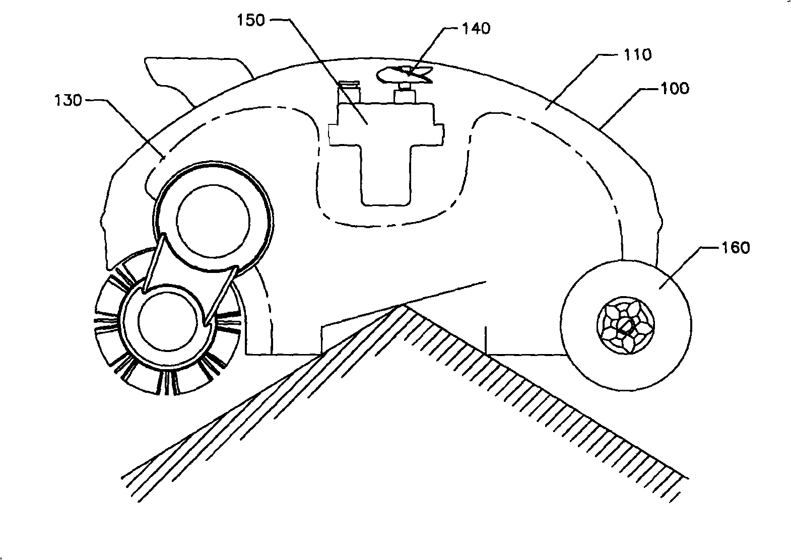
[0028] The basic idea of ​​the present invention is to set the bottom of the pool cleaning machine as an inwardly curved concave surface to ensure smooth passage of underwater obstacles. Further, the water inlet is arranged on the outer casing adjacent to the wheel and / or the roller position, which not only ensures the normal movement of the pool cleaner during underwater operation, but also ensures that the dirty water with dirt at the bottom of the pool is sucked into the in the cleaning machine.

[0029] Figure 4 The composition structure of the pool cleaning machine provided in the first emb...


PUM


Abstract

The invention discloses a water pool cleaning machine which comprises an outer shell, a containing space formed in the interior of the cleaning machine, at least one water inlet arranged on the outer shell, at least one water outlet arranged on the outer shell, a plurality of wheels or rollers or wheels and rollers for matching arranged at the bottom of the outer shell; the bottom of the outer shell appears to be an incurved concave surface. By setting the bottom of the water pool cleaning machine to be an incurved concave surface, the invention causes the water pool cleaning machine to be able to smoothly pass when running into barriers at the bottom of a pool during underwater operation, which reduces the fault rate and the maintenance cost of the water pool cleaning machine and improves the working efficiency of the water pool cleaning machine without influencing negative pressure and water flow needed by the water inlet. Ulteriorly, the water inlet is arranged at the proper position of the outer shell of the water pool cleaning machine, such as close to the wheels and / or rollers, thereby ensuring the water inlet to suck sewage with deposits into the water pool cleaning machine.

Description

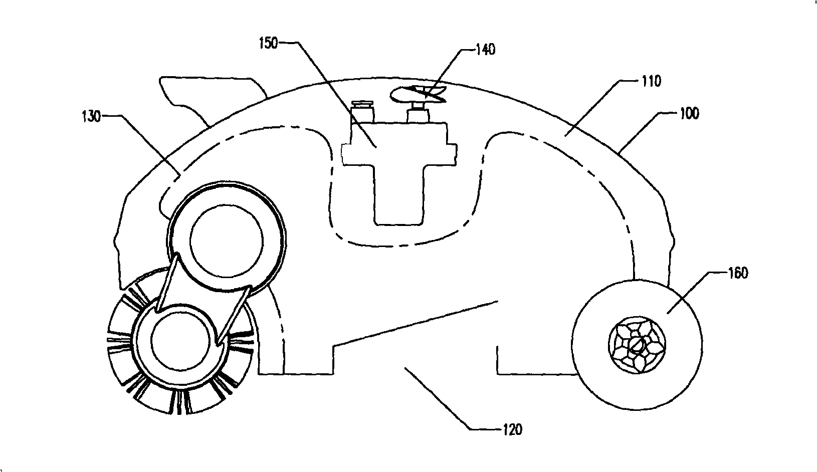
technical field [0001] The present invention relates to a pool cleaning device, in particular to the improvement of its bottom so as to prevent the pool cleaning machine from being stuck on the obstacle at the bottom of the pool and unable to move because the bottom is too low when the pool cleaning machine is working underwater. Background technique [0002] At present, the pool cleaners used for swimming pools etc. are generally divided into wheel type, drum type, chain belt type or liquid jet pool cleaners, generally as figure 1 As shown, the components include: an outer casing 100, which forms an accommodating space 110 inside; at least one water inlet 120, arranged on the outer casing 100; at least one filter bag 130, arranged in the container of the outer casing 100 placed in the space 110, and filter the water in the water inlet 120; at least one water outlet 140 is arranged on the outer casing 100 and at least one water pump 150 is correspondingly arranged in the at ...

Claims


Application Information

Patent Timeline
Patent Type & Authority Applications(China)
IPC IPC(8): E04H4/16
CPCE04H4/1654
Inventor 许永健许方敏
Owner SMARTPOOL
Learn More