Electric-controlled pneumatic type clutch booster unit and operating method thereof

A clutch and pneumatic technology, applied in fluid-driven clutches, non-mechanical-driven clutches, clutches, etc., can solve problems such as clutch master cylinder and clutch booster failure

Active Publication Date: 2008-10-08
RUILI GROUP RUIAN AUTO PARTS CO LTD
View PDF1 Cites 8 Cited by
  • Summary
  • Abstract
  • Description
  • Claims
  • Application Information

AI Technical Summary

Problems solved by technology

Since this system cancels the traditional hydraulic control function, the whole vehicle is no longer equipped with a clutch master cylinder, thus effectively solving the problem of early failure of the clutch master cylinder and clutch booster caused by the clutch hydraulic control system for a long time

Method used


Image

  • Electric-controlled pneumatic type clutch booster unit and operating method thereof
  • Electric-controlled pneumatic type clutch booster unit and operating method thereof

Examples


Embodiment approach 1

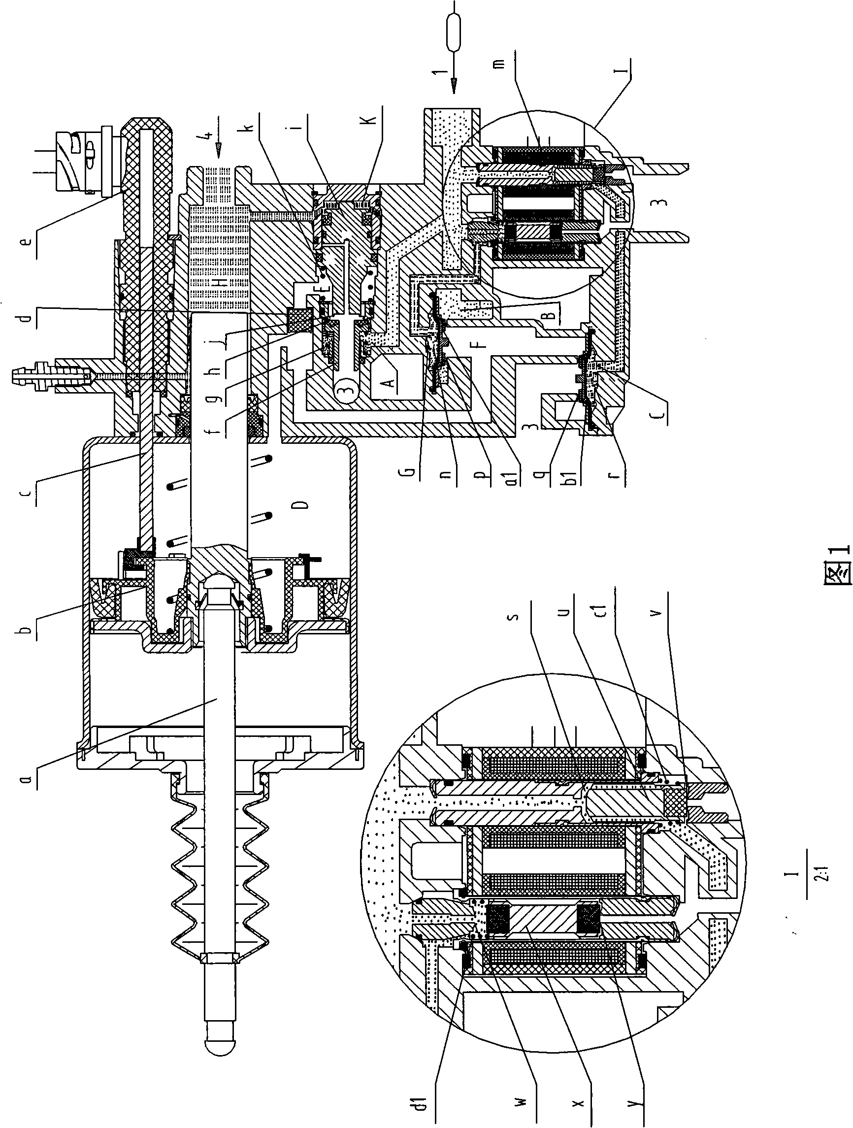
[0016] Embodiment 1: Pneumatic clutch booster device with hydraulic control mechanism and electronic control mechanism

[0017] Structural description (refer to accompanying drawing 1):

[0018] A friction clutch consists of a diaphragm spring and a release lever. The high-pressure gas is input from the air pressure input port, and the complex gas path is connected with the air pressure input port and the fourth air pressure chamber D. Multiple valves are arranged on the complex gas path, and the hydraulic control device and the electric control device control the opening and closing of these valves respectively. Control, so as to control the flow path of the high-pressure gas, when the high-pressure gas reaches the fourth air pressure chamber D, the high-pressure gas in the fourth air pressure chamber D pushes the clutch control piston b and then drives the push rod a to move to the left, the push rod a and the clutch The release lever is connected, thereby realizing the di...

Embodiment approach 2

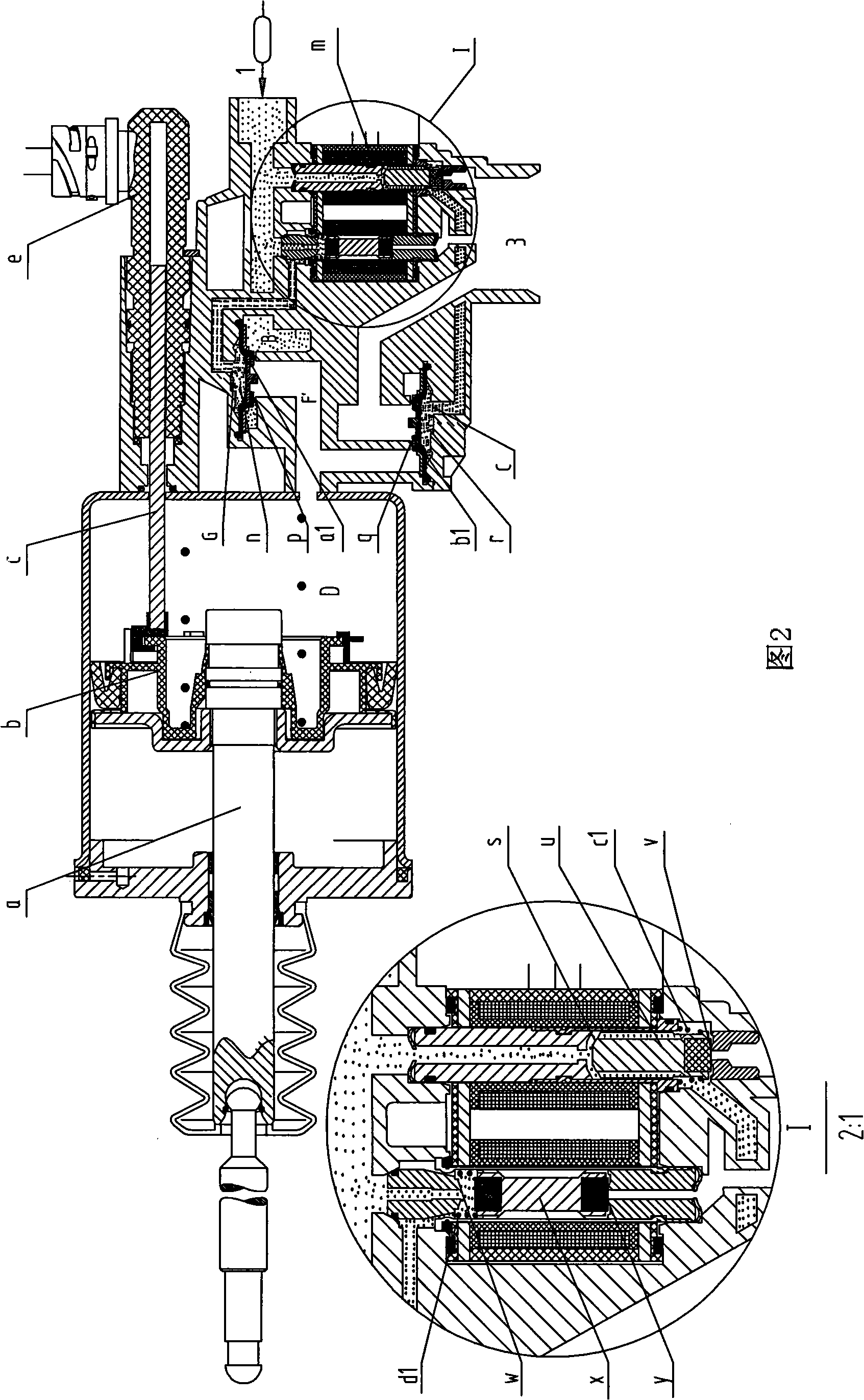
[0043] Embodiment 2: Pneumatic clutch booster device with only electronic control mechanism

[0044] Structural description (refer to accompanying drawing 2):

[0045] This embodiment omits the part of the hydraulic control mechanism and the associated high-pressure gas path and air pressure chamber in the first embodiment, and only keeps the part related to the electric control control mechanism to control the clutch.

[0046] The air pressure input port 1 directly communicates with the second air pressure chamber B, and the second air pressure chamber B communicates with the sixth air pressure chamber F' through the intake valve a1. When the intake valve a1 is opened, the high-pressure gas in the second air pressure chamber B passes through the inlet The valve p enters the sixth air pressure chamber F', and then enters the fourth air pressure chamber D. The sixth air pressure chamber F' communicates with the air pressure output port 3 through the exhaust valve b1. When th...


PUM


Abstract

The invention relates to a pneumatic clutch booster device and an operation method thereof. The device adopts a pure-electric control model to realize the operation of the clutch, and aims at simplifying the structure of the clutch booster and reducing failure rate. The clutch can also be separately controlled by a hydraulic operating mechanism and an electrical control operation mechanism to realize the diversity of vehicles during shifting process, which can, on one hand, realize the leave and joint of the clutch through a traditional clutch hydraulic operating mechanism, and on the other hand, realize the operation of the clutch directly through an electrical control manner, so as to reduce the working frequency of the clutch hydraulic operating mechanism and enhance the quality and service life of the clutch booster device. The pneumatic clutch booster device of the invention is also provided with an attrition alarm device of a clutch friction disc; the attrition alarm device can monitor the attrition condition of the clutch friction disc and emit an alarm signal when the attrition value reach a preset value to remind the user to change the friction disc; the attrition alarm device can also effectively judge the leave and joint status of the clutch.

Description

technical field [0001] The invention relates to a clutch booster device and its operating method, and in particular to an electric-controlled pneumatic clutch booster device and its operating method. Background technique [0002] Friction clutches are widely used in transmission systems of various vehicles. Up to now, the operation forms of friction clutches have become more and more diversified, mainly including electric and electronic control type with motor as the power source, electronic control hydraulic type with hydraulic pressure as power, and hydraulic control pneumatic type with air pressure as power. Among them, the pneumatic type has been used more and more due to its advantages of low cost, simple structure, and environmental protection, especially in medium and heavy commercial vehicles and large passenger vehicles with their own air source (air brake). Broad prospects. [0003] In the traditional pneumatic clutches that use air pressure as the power source t...

Claims


Application Information

Patent Timeline
Patent Type & Authority Applications(China)
IPC IPC(8): F16D25/08
Inventor 瞿昌贵李传武杨柳
Owner RUILI GROUP RUIAN AUTO PARTS CO LTD
Why Eureka
Try Eureka