Exhaust gas purifying device and purification method thereof

An exhaust gas purification device and a technology for exhaust gas purification, which are used in exhaust devices, chemical instruments and methods, mufflers, etc.

Inactive Publication Date: 2008-10-08
卢冠均
View PDF0 Cites 8 Cited by
  • Summary
  • Abstract
  • Description
  • Claims
  • Application Information

AI Technical Summary

Problems solved by technology

However, there is no purification device with a simple structure that can efficiently purify the exhaust gas discharged from the combustion furnace.

Method used


Image

  • Exhaust gas purifying device and purification method thereof
  • Exhaust gas purifying device and purification method thereof

Examples


Embodiment Construction

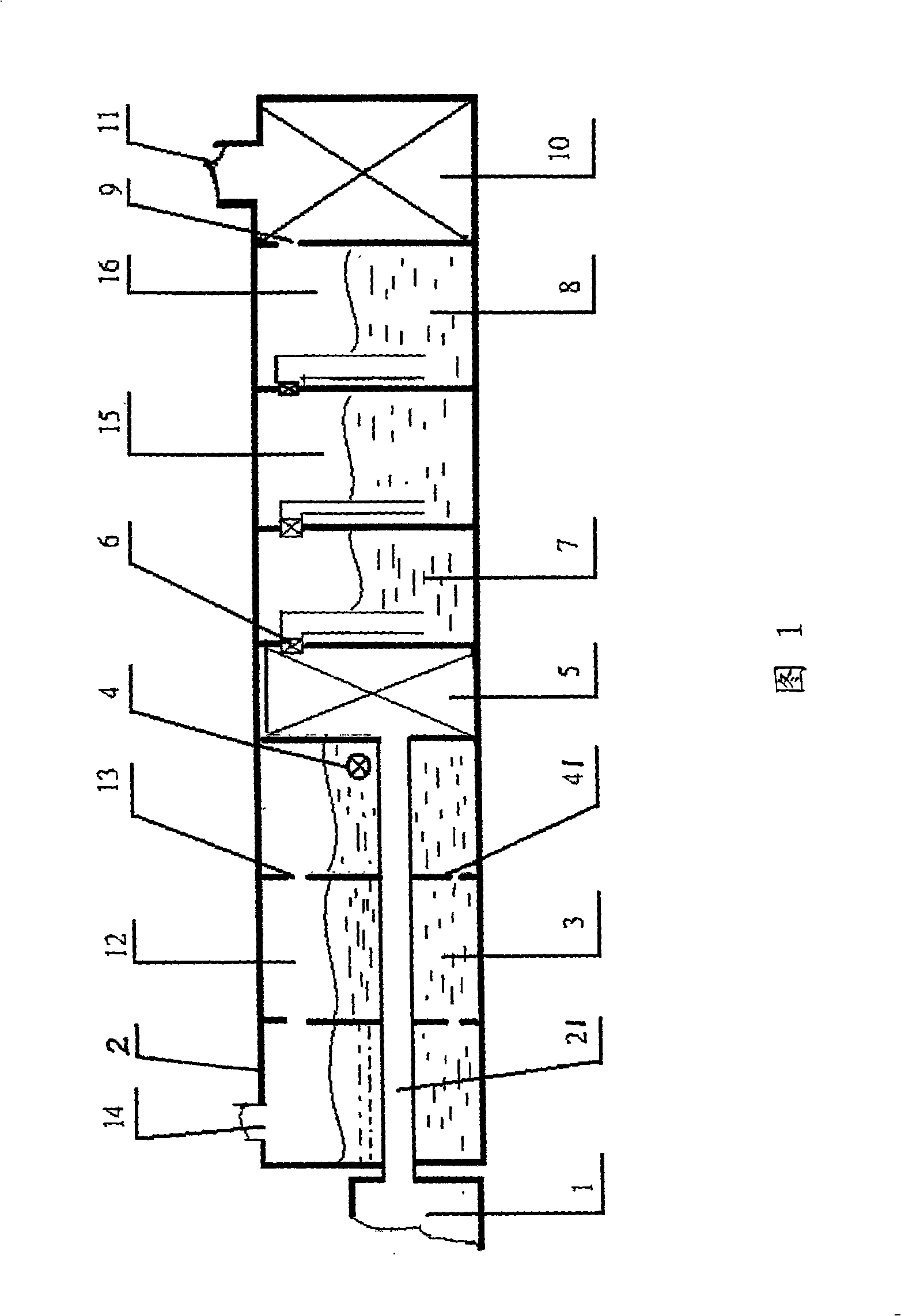
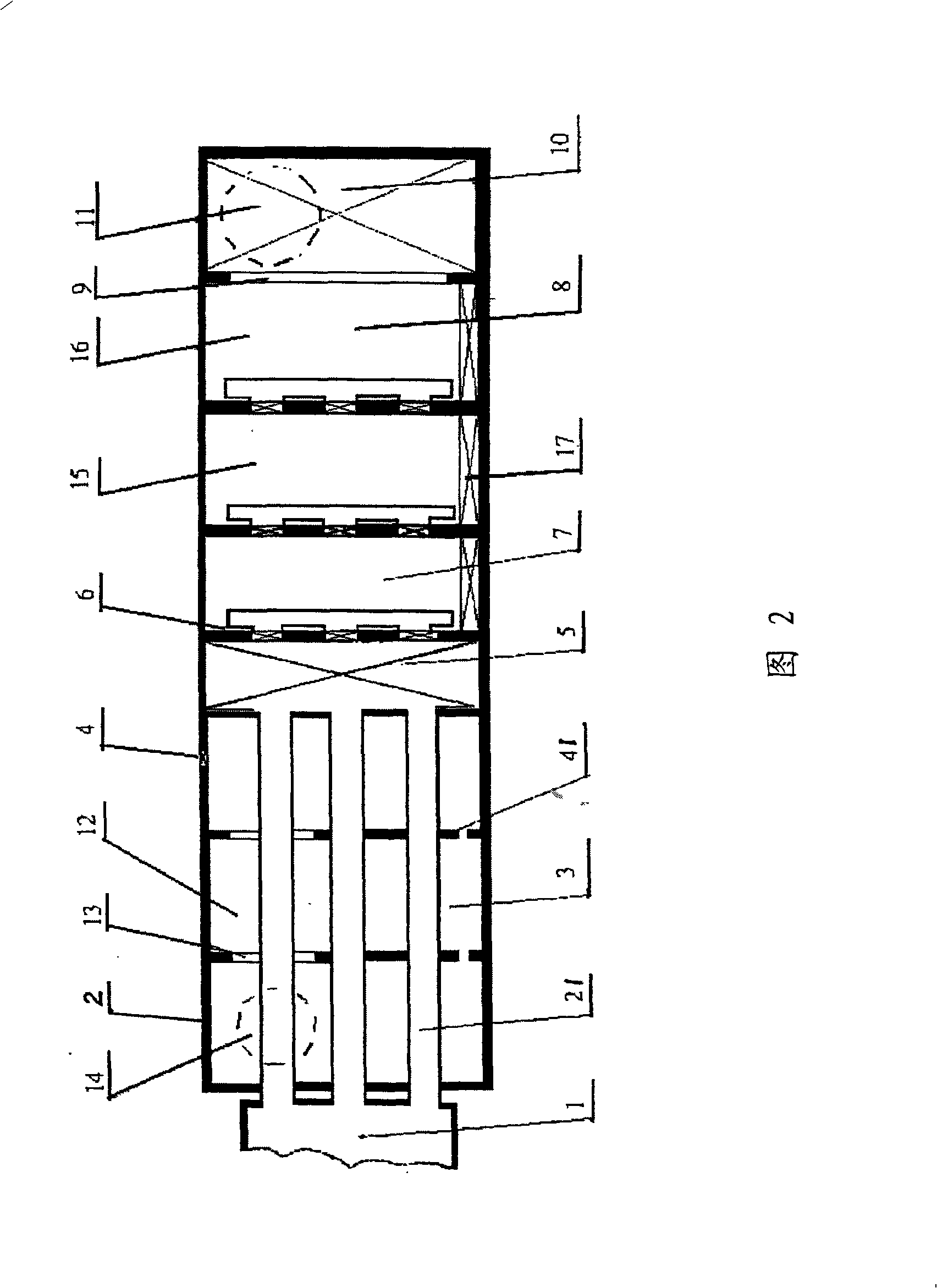
[0013] As shown in FIG. 1 , the exhaust gas purification device of the present invention includes: a cooling unit 2 , a dust removal unit 5 and an absorption unit 15 . The exhaust gas cooling unit 2 includes: a cooling chamber 12 containing a cooling liquid 3 , such as cooling water; and an exhaust gas transmission pipe 21 passing through the cooling chamber, wherein high-temperature exhaust gas is transmitted. The exhaust gas transmission pipe 21 is immersed in the cooling liquid 3 so that the high-temperature exhaust gas transmitted therein can exchange heat with the external cooling liquid to cool the high-temperature exhaust gas. A plurality of exhaust gas transmission pipes 21 may also be arranged in the cooling chamber 12, as shown in FIG. 2, three exhaust gas transmission pipes are arranged in the cooling chamber 12, and each exhaust gas transmission pipe is immersed in the cooling liquid. The cooling chamber 12 may also be provided with a cooling liquid level regulatin...


PUM

PropertyMeasurementUnit
melting pointaaaaaaaaaa

Abstract

The invention discloses a waste gas purifier, including a cooling unit with a cooling room for containing liquid coolant and a waste gas transfer tube penetrating the cooling room and immerged into the liquid coolant, the cooling unit is used for cooling waste gas inputted into the transfer tube; a dust removing unit arranged on backward position side of the cooling unit for removing harmful substance and flour dust contained in the waste gas; a absorption unit arranged on backward position side of the dust removing unit and containing the absorption liquid, for removing carbonic anhydride and precipitate from the waste gas by reacting the absorption liquid with the carbonic anhydride and precipitate in the waste gas to generate precipitate; and a purification unit arranged on backward position side of the absorption unit and containing purified water for removing remained harmful substance and flour dust in the waste gas. The invention also discloses an exhaust gas cleaning method.

Description

technical field [0001] The present invention relates to an exhaust gas purification device and its purification method, more specifically, to an exhaust gas purification device and its purification method, which can be used to remove dust, carbon dioxide, sulfide and other harmful substances contained in the exhaust gas to purify exhaust gas. Background technique [0002] With the development of society, people's awareness of environmental protection is getting stronger and stronger. However, humans burn fossil fuels, petroleum products, and organic matter in order to obtain more energy, but produce a large amount of waste gas containing dust, carbon dioxide, sulfide, and harmful substances, such as dioxins (PCDD), TCDD, and dioxins. The dust in the exhaust gas leads to the deterioration of air quality; carbon dioxide causes the greenhouse effect, making the global climate warmer; sulfides produce acid rain, which leads to soil acidification, mineral loss, and affects plant...

Claims


Application Information

Patent Timeline
Patent Type & Authority Applications(China)
IPC IPC(8): F23J15/00
CPCB01D53/504B01D2257/504F01N3/043Y02C10/04B01D53/62B01D2251/404F01N3/005F01N3/021B01D2257/304B01D53/78B01D2251/604Y02T10/20Y02E20/32Y02T10/12Y02A50/20Y02C20/40
Inventor 卢冠均
Owner 卢冠均
Why Eureka
Try Eureka