
Pre-water filling steel tube hydraulic test method and special-purpose equipment thereof

A technology of hydrostatic testing and special equipment, which is applied in the direction of liquid tightness measurement by using liquid/vacuum degree, and by measuring the increase and deceleration rate of fluid, etc., which can solve the problems of low efficiency and high production cost, and reduce the occupied area , save costs, and improve the effect of suppressing production efficiency

Inactive Publication Date: 2008-10-08
烟台鲁宝钢管有限责任公司
View PDF0 Cites 14 Cited by
  • Summary
  • Abstract
  • Description
  • Claims
  • Application Information

AI Technical Summary

Problems solved by technology

[0007] The invention mainly solves the problems of low efficiency and high production cost of the existing steel pipe hydraulic test method

Method used


Image

  • Pre-water filling steel tube hydraulic test method and special-purpose equipment thereof
  • Pre-water filling steel tube hydraulic test method and special-purpose equipment thereof

Examples


Embodiment 1

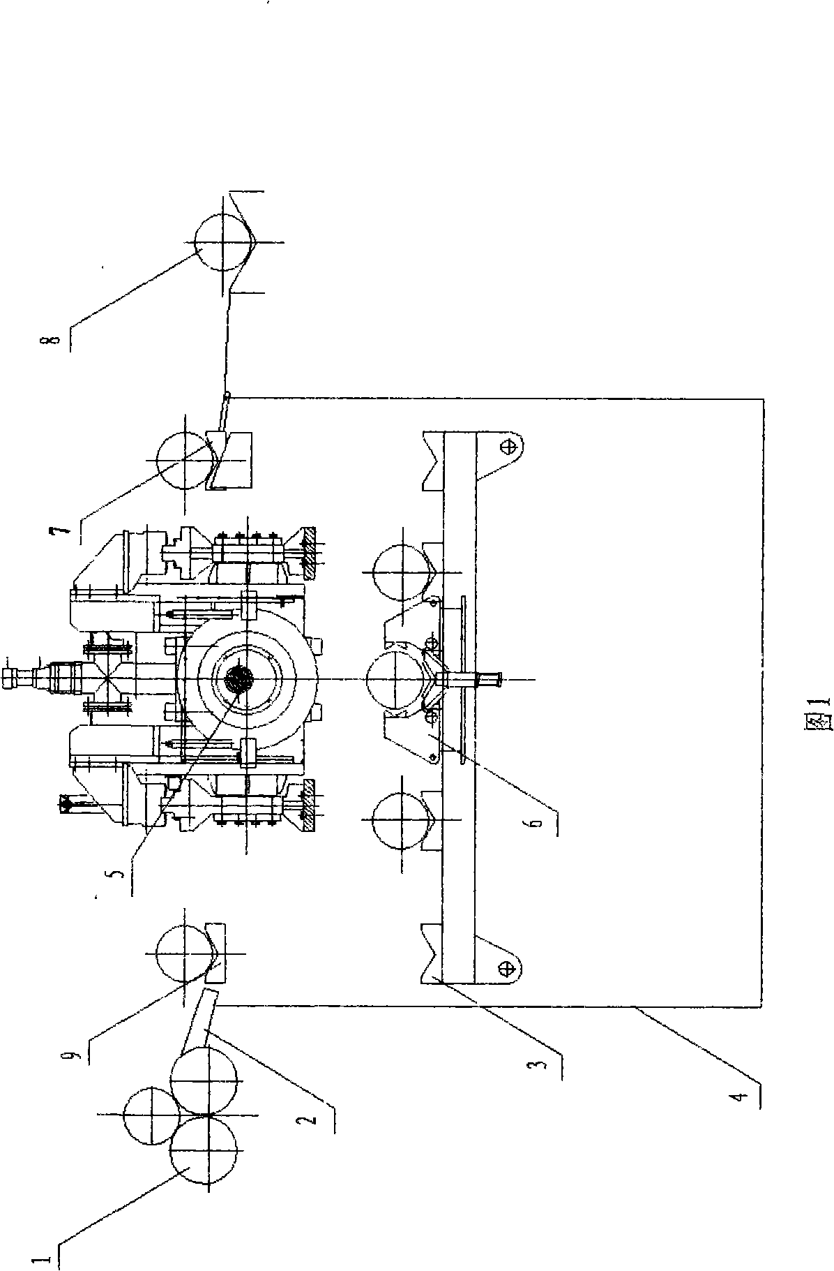
[0019] Embodiment 1, referring to Fig. 3, is processed into a medium box 4, the medium is generally an anti-rust floating liquid, a pipe transfer mechanism 3 is installed in the medium box 4, and a clamping mechanism 6 is installed on the pipette mechanism 3, and the clamping mechanism 6 It can be lifted and lowered, and a hydraulic test mechanism 5 is installed above the pipe transfer mechanism 3, and a lifting mechanism 9 and a discharge mechanism 7 are respectively installed above the two ends of the pipe transfer mechanism 3. The discharge mechanism 7 can be lifted, and the other end of the discharge mechanism 7 Install the empty water mechanism 8, the two are connected, install the feeding mechanism 2 between the lifting mechanism 9 and the rotary flushing mechanism 1, one end of the feeding mechanism 2 is connected with the rotary flushing mechanism 1, and the other end is connected with the lifting mechanism 9 .

[0020] Use the above-mentioned equipment to carry out th...

Embodiment 2

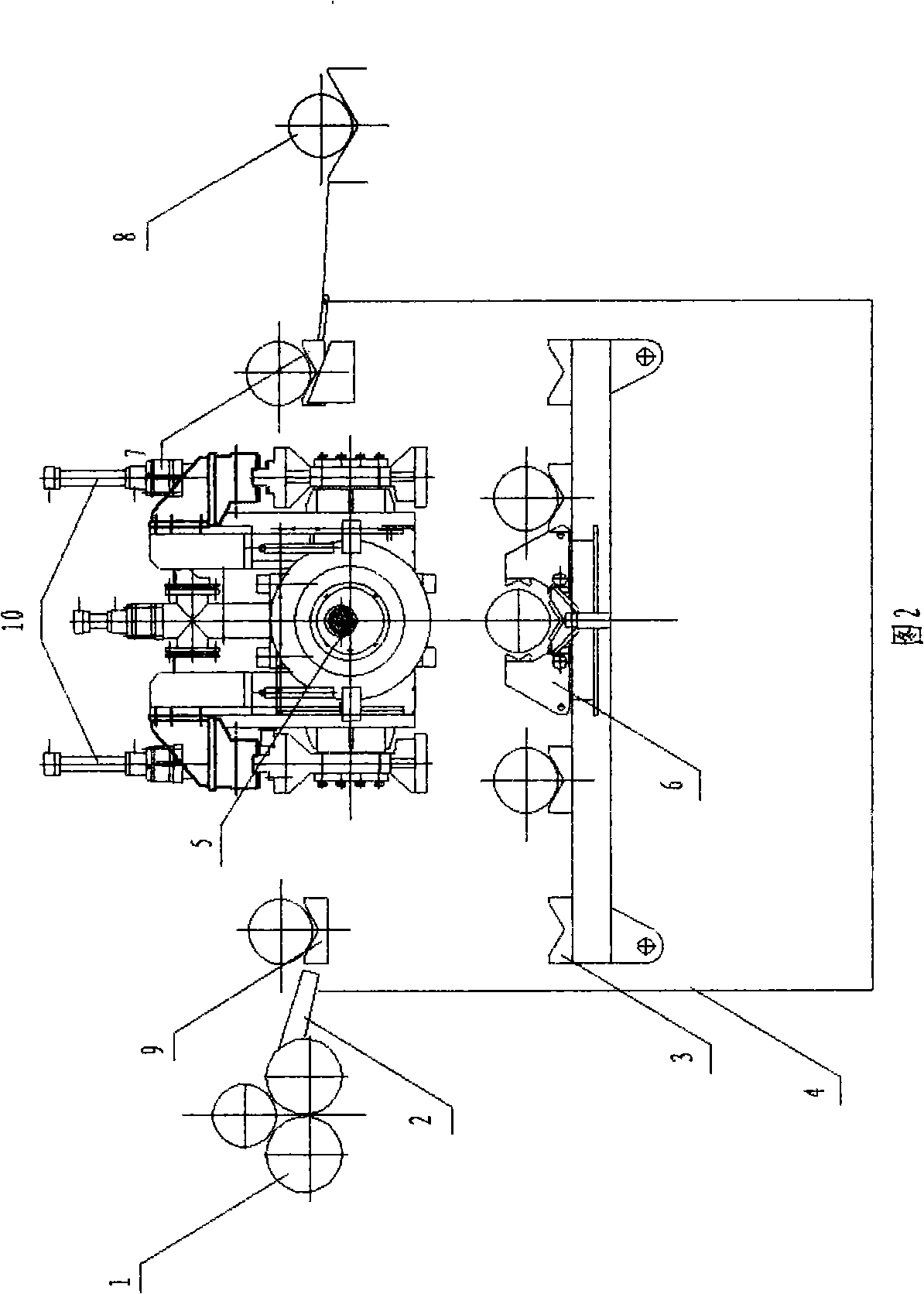
[0021] Embodiment 2, referring to Fig. 4, is the same as Embodiment 1, except that the clamping mechanism 6 does not lift up and down, and a pressure beam lifting mechanism 10 is set on the hydraulic pressure test mechanism 5, and the pressure beam lifting mechanism 10 drives the hydraulic pressure test mechanism 5. Press mechanism 5 can lift.

[0022] Using the equipment in Example 2, the specific actions of the pre-filled steel pipe hydraulic test method are as follows: first, the steel pipe is rinsed on the rotary flushing mechanism 1 to remove foreign matter on the inner surface of the steel pipe, and the action of the feeding mechanism 2 will flush the steel pipe after the flushing is completed. The steel pipe is sent to the lifting mechanism 9, and the lifting mechanism 9 descends to put the steel pipe on the pipe transfer mechanism 3. At this time, the steel pipe has been completely immersed in the hydraulic medium in the water tank 4 and filled with the hydraulic medium...


PUM


Abstract

The invention discloses a hydrostatic test method and the dedicated device thereof for a water pre-filling steel pipe, comprising a rotary type washing mechanism (1) connected with one end of a feed mechanism (2), the other end of the feed mechanism (2) is connected with a elevating mechanism (9), a media tank (4) is arranged below the elevating mechanism (9), a pipe-moving mechanism (3) is arranged in the media tank (4),a clamping mechanism (6) is arranged on the pipe-moving mechanism (3), a hydrostatic test mechanism (5) is arranged above the clamping mechanism (6),the pipe-moving mechanism (3) is corresponding to a discharging mechanism (7) arranged upside, the discharging mechanism (7)is connected with a water control mechanism (8);the hydrostatic test method utilizing the device is showed as follows: rinsing the internal surface of the steel pipe, immerging the steel pipe in bulge medium, sealing the two ends of the steel pipe by a bulge head when the inside cavity of the steel pipe is filled with bulge medium, bulging and dwelling directly, and then discharging last; the method mentioned above does not take up the effective operation time and the device has high hydrostatic test efficiency.

Description

Technical field: [0001] The invention relates to the technical field of hydraulic test of steel pipes, in particular to a method for hydraulic test of steel pipes filled with water and special equipment thereof. Background technique: [0002] At present, the hydrostatic test of steel pipes generally adopts hydraulic testing machines, which are used to test the compactness and pressure bearing capacity of steel pipes. [0003] The principle of the hydrostatic test: Use a special hydrostatic test head to seal the two ends of the steel pipe, and fill the steel pipe body with a liquid pressure medium (usually an emulsion with the rust-proof function of the steel pipe, hereinafter referred to as "water") ), and then pressurize. When the pressure in the pipe body reaches a given pressure and continues to maintain the pressure for a specified time or the stroke of the booster cylinder that uses supplementary pressure is less than the specified value, it is considered that there is ...

Claims


Application Information

Patent Timeline
IPC IPC(8): G01M3/28
Inventor 王旭午李学进
Owner 烟台鲁宝钢管有限责任公司
Learn More