Twist drill

A twist drill and drill tip technology, which is applied in twist drills, drilling tool accessories, drilling/drilling equipment, etc., can solve the problems of material plasticization and achieve favorable pressure distribution effects

Active Publication Date: 2008-10-08
天窗工具有限公司
View PDF2 Cites 23 Cited by
  • Summary
  • Abstract
  • Description
  • Claims
  • Application Information

AI Technical Summary

Problems solved by technology

Therefore, the method does not directly address the plasticization of m

Method used


Image

  • Twist drill
  • Twist drill
  • Twist drill

Examples


Embodiment Construction

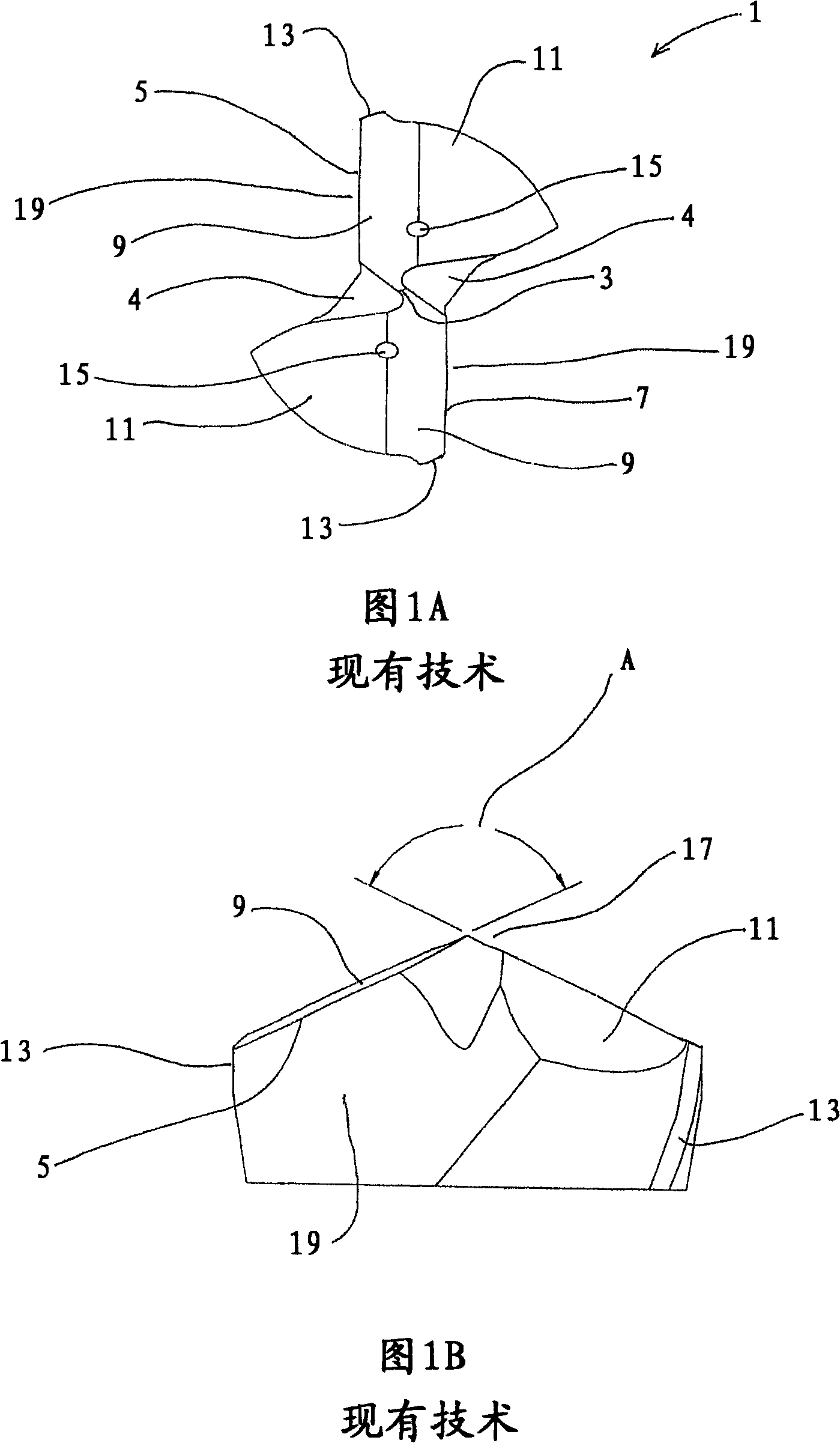
[0117] Figure 1 shows the cutting end of a conventional twist drill, such as the CDX twist drill manufactured by Dormer Tools (Sheffield) Ltd. This drill has been discussed above.

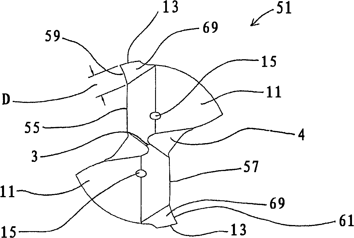
[0118] Figure 2A and 2B An embodiment of the invention is shown wherein the metalworking twist drill is made of cemented carbide. Other materials are also possible, such as HSS and the like.

[0119] The cutting bit 51 of the twist drill has many features in common with the conventional twist drill shown in Figures 1A and 1B, and the same reference numerals are used to denote common features.

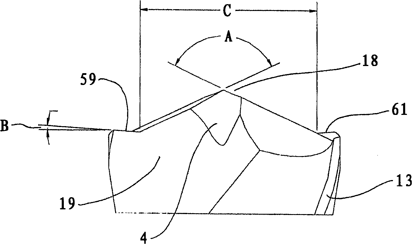
[0120] This embodiment differs from the conventional twist drill of Fig. 1 in that the cutting edges comprise inner cutting edges 55, 57 and outer cutting portions 59, 61 located radially outside these inner parts.

[0121] The inner cutting edge forms a drill point 18, which has a positive angle A, in this case 130°. Other point angles can also be used, preferably in the range of 115° to 155°.

[012...


PUM


Abstract

A metal-working twist drill is provided with inner cutting edges that form a point (18) having an angle, A, of 130 degrees . An outer, peripheral, part of each cutting edge (55, 57) forms an outer cutting portion (59, 61). The outer cutting portions slope in the opposite direction to the corresponding inner cutting edges and form an angle B, of 3 degrees with respect to a plane normal to the axis of rotation of the twist drill. The width of the outer cutting portion, D as measured at the cutting edge, is 10.5% of the diameter of the twist drill. The metal-working twist drill produces bores having a reduced exit burr height.

Description

technical field [0001] The invention relates to twist drills, in particular to hard alloy twist drills with flutes for cutting metals and composite materials. Background technique [0002] Twist drills (also known as twist drill bits) include at one end a shank for attachment to a device that turns the drill, such as a drill chuck, and an opposite end includes a cutting edge for cutting into the hole to be drilled or machined. A cutting tip in a material such as a workpiece. For metalworking twist drills for drilling metal workpieces, the cutting edge typically extends generally radially from the central portion of the cutting bit to the outer edge of the cutting bit. Between the shank and the bit, there is usually a body with flutes that provide stability to the twist drill as it forms a hole and help remove material drilled from the hole. [0003] A large number of twist drill designs are known, and the geometry of the cutting bit is designed according to the specific wo...

Claims


Application Information

Patent Timeline
IPC IPC(8): B23B51/02
CPCB23B2251/14Y10T408/78B23B2251/18B23B2251/04B23B2226/27Y10T408/81Y10T408/9097B23B51/02B23B2250/12Y10T408/906Y10T408/899B23P15/32B24B3/26
Inventor 大卫·古尔伯恩
Owner 天窗工具有限公司
Why Eureka
Try Eureka