Hand machine tool

A technology of hand-held machine tools and handle shells, which is applied in the direction of manufacturing tools and portable mobile devices, which can solve problems such as complex structures and achieve the effect of eliminating damage

Inactive Publication Date: 2008-10-08
AEG ELECTRIC TOOLS
View PDF1 Cites 4 Cited by
  • Summary
  • Abstract
  • Description
  • Claims
  • Application Information

AI Technical Summary

Problems solved by technology

[0003] The above arrangement structure requires a large structural space in the axial direction and radial direction, and the structure is complex

Method used


Image

  • Hand machine tool
  • Hand machine tool
  • Hand machine tool

Examples


Embodiment Construction

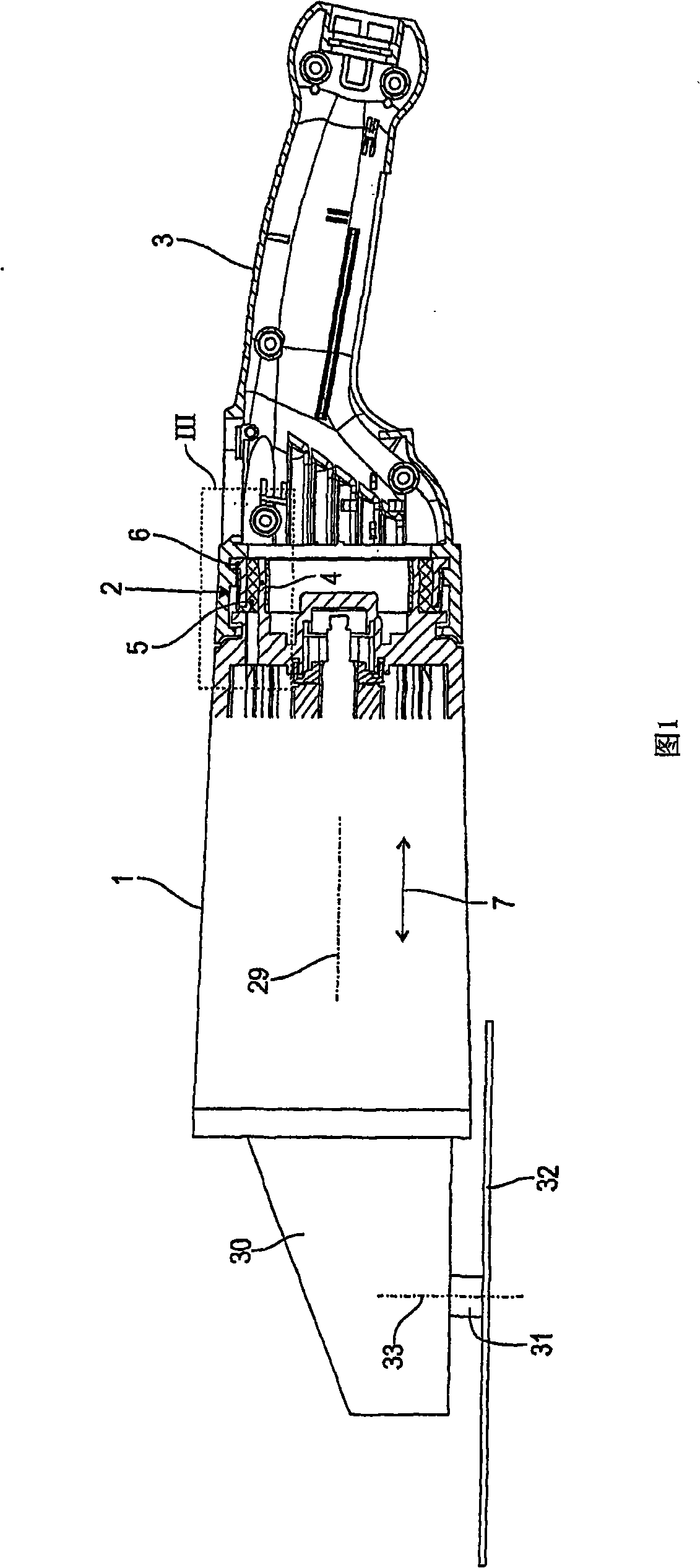
[0023] FIG. 1 shows a hand-held power tool according to the invention, such as an angle grinder, in a partial side view. In the motor housing 1 of the power tool there is an electric motor, not shown in detail, which drives a tool, such as a cutting wheel 32 , by means of a bevel gear, also not shown, which is accommodated in the gear housing 30 . The cutting wheel 32 is mounted on a cutter shaft 31 driven in rotation about an axis 33 approximately perpendicular to the longitudinal axis 29 of the approximately cylindrical (here slightly conical) motor housing 1 . On the side of the motor housing 1 opposite the transmission housing 30 , there is a handle housing 3 which can accommodate the control elements of the drive motor and forms the rear handle of the power tool.

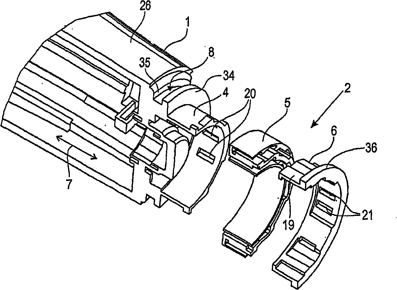
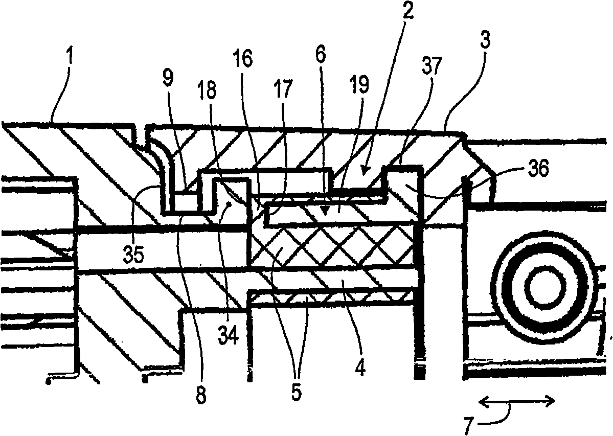
[0024] During operation, the driving motor and the cutting wheel 32 generate vibrations, which are transmitted to the motor housing 1 and components mounted on the motor housing. In order to isolate vibration...


PUM


Abstract

The invention relates to a portable power tool having a motor housing (1) and a separate handle housing (3) fastened to the motor housing (1) by means of an elastic vibration damper (2) and secured thereon in a positive-locking manner. The vibration damper (2) is composed of a fastening sleeve (4) assigned to the motor housing (1), an elastic damping sleeve (5) coaxially enclosing the fastening sleeve (4) and a handle holder (6) likewise coaxially enclosing the fastening sleeve (4) and the damping sleeve (5) and assigned to the handle housing (3). The essentially rigid construction unit consisting of the handle holder (6) and the handle housing (3) is secured in a positive-locking manner, with play, directly to the essentially rigid construction unit consisting of the fastening sleeve (4) and the motor housing (1).

Description

technical field [0001] The invention relates to a hand-held power tool with a motor housing and a separate handle housing which is fastened to the motor housing by means of an elastic damper and fastened to the damper in a form-fitting manner. Background technique [0002] A hand-held power tool of this type is known from WO 2004 / 039541 A1. In order to prevent the transmission of the vibrations that occur during operation of such a machine tool to the handle housing, this document proposes a vibration damper. The shock absorber has a bracket on the side of the motor housing and a mounting plate on the side of the handle housing, an annular buffer element is arranged axially between the bracket and the mounting plate. The three components of the shock absorber lie axially one above the other and are axially penetrated by fastening elements in the form of screws. The mounting plate is fastened on the fastener in a form fit manner, which prevents the rear handle fixed on the ...

Claims


Application Information

Patent Timeline
Patent Type & Authority Applications(China)
IPC IPC(8): B25F5/00
CPCB25F5/006
Inventor A·艾森哈特H·法尔讷
Owner AEG ELECTRIC TOOLS
Why Eureka
Try Eureka