
Method and rock drilling rig for hole drilling

A technology for rock drilling and equipment, which is used in the field of drilling and rock drilling equipment, and can solve the problems of heavy base and large static force of rotary drilling equipment

Inactive Publication Date: 2008-10-08
SANDVIK MINING & CONSTR OY
View PDF0 Cites 3 Cited by
  • Summary
  • Abstract
  • Description
  • Claims
  • Application Information

AI Technical Summary

Problems solved by technology

These have the problem that rock fragmentation requires extreme static forces and therefore these so called rotary drilling rigs are heavy and require a solid foundation

Method used


Image

  • Method and rock drilling rig for hole drilling
  • Method and rock drilling rig for hole drilling
  • Method and rock drilling rig for hole drilling

Examples


Embodiment Construction

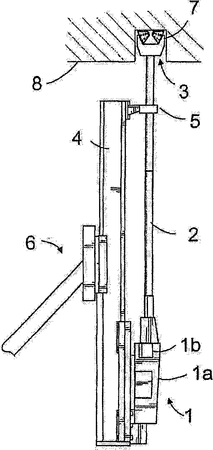
[0014] The figures show a tophammer rock drilling apparatus comprising a rock drilling machine 1 , a drill rod 2 connected to the rock drilling machine and a conical roller cone bit 3 connected at the end of the drill rod. The rock drilling machine 1 includes a percussion device 1a and a rotary motor 1b. The impact device 1a transmits impact to the cone bit 3 via the drill rod 2, and accordingly, the rotary motor 1b rotates the drill rod and the cone bit 3 together therewith. Their structure and operation are known per se, so a more detailed description of them is not required.

[0015] Generally, the percussion device is moved along the feed beam 4 in a manner known per se and by means of a feed mechanism known per se, at the end of which there is usually a drilling guide 5, which Serves to guide the drill rod and thus the drill bit during drilling. The feed beam 4 is in turn usually connected to the base of the rock drilling rig (not shown) together with a boom 6 or the li...


PUM


Abstract

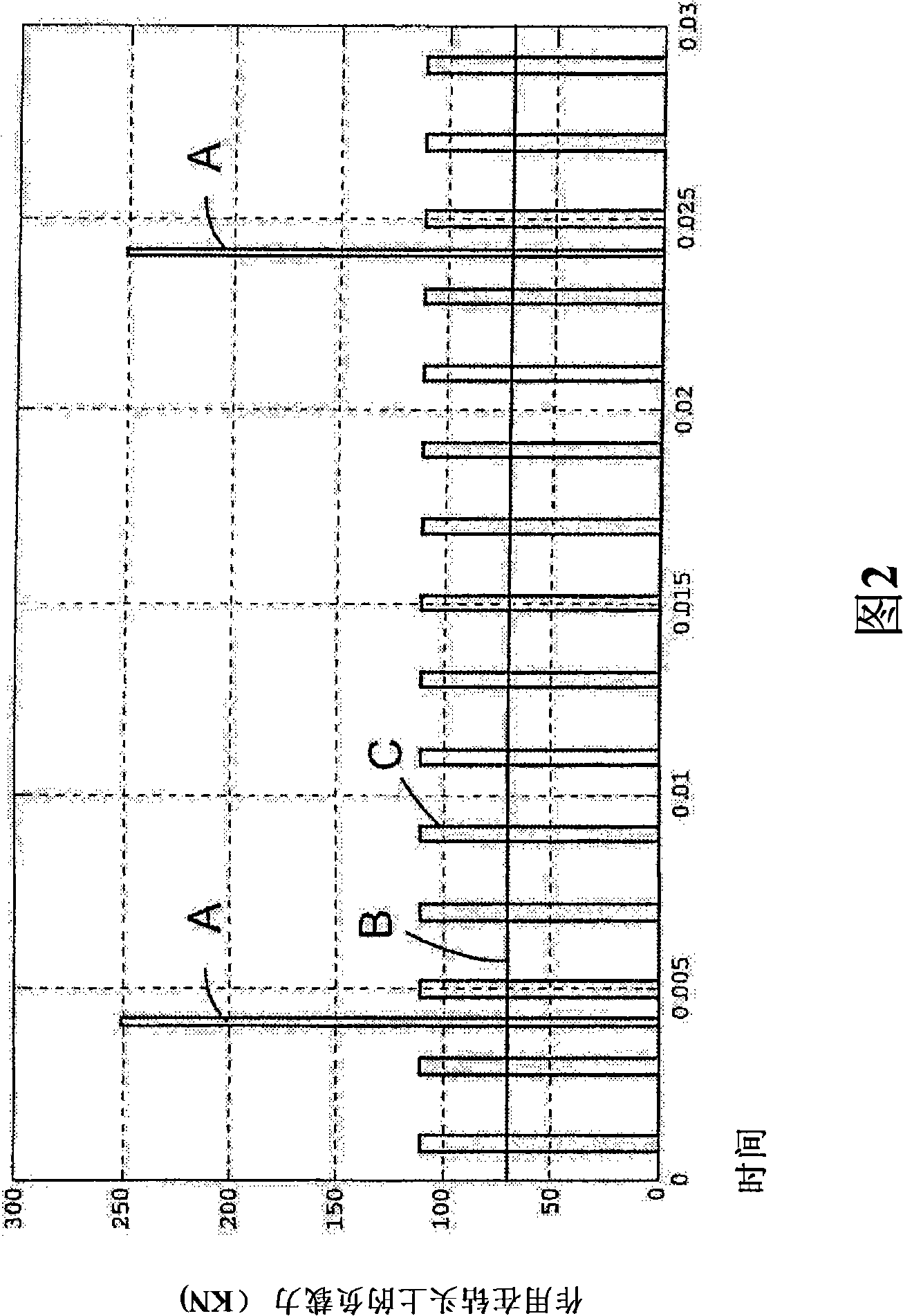
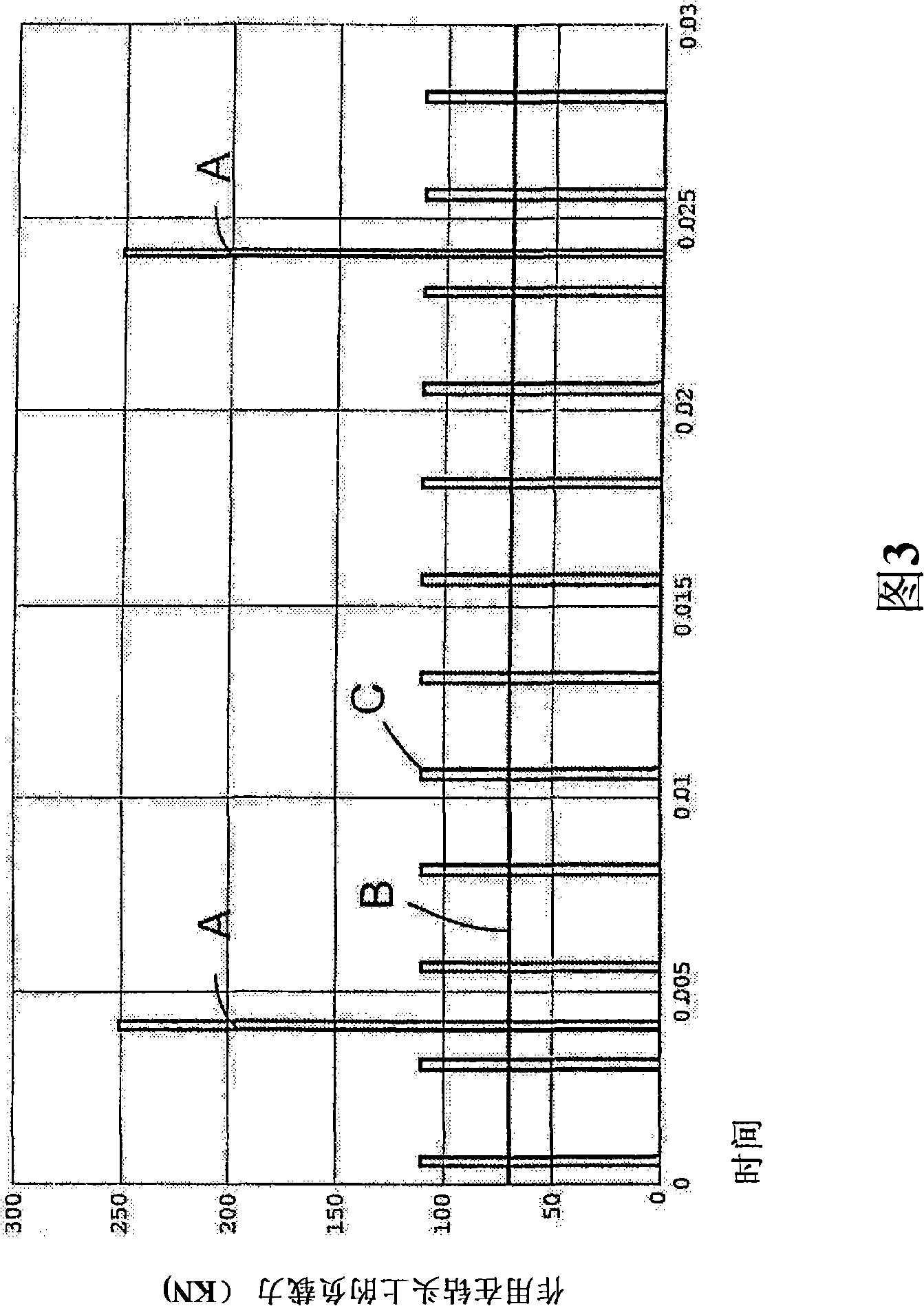
The invention relates to a method and a rock-drilling rig for drilling a hole in a rock. In the method the hole is drilled with a so-called top-hammer rock-drilling rig including a drill rod and a cone roller bit at the end of the drill rod. During drilling with the percussion device, stress pulses of low amplitude are produced at a high frequency of at least 200 Hz. In the rock drilling rig, the cone roller bit (3) at the end of the drill rod and the percussion device are configured to feed stress pulses of low amplitude, at the frequency of at least 200 Hz, via the drill rod and the cone roller bit to the rock.

Description

technical field [0001] The present invention relates to a method of drilling holes in rocks using a top hammer rock drilling device, the top hammer rock drilling device comprising a rock drilling machine to which a drill rod is connected and a drill bit is connected to one end of the drill rod , and the rock drilling machine includes a percussion device and a rotary motor, in this method, the drill rod and the drill bit are rotated together with the rotary motor, and the stress pulse is guided to the rock by the percussion device via the drill rod and the drill bit for breaking the rock . The invention also relates to rock drilling equipment for drilling holes in rock, said rock drilling equipment comprising a tophammer rock drilling machine, a drill rod connected to the rock drilling machine and a drill bit connected to the end of the drill rod, and said A rock drilling machine includes a percussion device for providing stress pulses to the rock via a drill rod and a drill b...

Claims


Application Information

Patent Timeline
Patent Type & Authority Applications(China)
IPC IPC(8): E21B6/00E21B7/24E21BE21B10/08
CPCE21B10/08E21B7/24E21B6/00
Inventor 马尔库·凯斯基尼瓦毛里·埃斯科约尔玛·梅基艾莫·海林尤哈·皮波宁埃尔基·阿霍拉
Owner SANDVIK MINING & CONSTR OY
Learn More