Fan and its impeller

A fan blade and impeller technology, applied in the field of fans and their impellers, can solve the problems of reducing the service life of the fan 1, increasing the noise, fatigue of unbalanced bearings or other parts, etc., so as to improve the efficiency, increase the elasticity, and avoid the resonance phenomenon. Effect

Inactive Publication Date: 2008-10-15
DELTA ELECTRONICS INC
View PDF0 Cites 16 Cited by
  • Summary
  • Abstract
  • Description
  • Claims
  • Application Information

AI Technical Summary

Problems solved by technology

[0004] For the design of the current fan 1, the selection of the number of the fan blades 101 is designed with an odd number, the purpose is to prevent the fan 1 from rotating with other components, such as the coil assembly 111 of the motor 11 or the fan frame 13. The upper rib 131 resonates, which leads to many problems, such as increased noise, unbalanced phenomenon, and increased fatigue of bearings or other parts, etc., thereby affecting the overall performance of the fan 1 and reducing the service life of the fan 1
[0005] However, due to the increasing demand for heat dissipation, the performance requirements of the fan 1 are also increasing. To improve the air volume and pressure, it is generally attempted to increase the air volume and air pressure by increasing the blade width of the fan blade 101. However, due to the relative There are restrictions on the angle setting between adjacent fan blades 101, so the design of the blade width is also limited
In addition, when it is desired to increase the number of fan blades 101 in order to increase the air volume and wind pressure, it will encounter the resonance phenomenon generated between the number of components.

Method used


Image

  • Fan and its impeller
  • Fan and its impeller
  • Fan and its impeller

Examples


Embodiment Construction

[0035] A fan and its impeller according to preferred embodiments of the present invention will be described below with reference to related drawings, wherein the same components will be described with the same reference symbols.

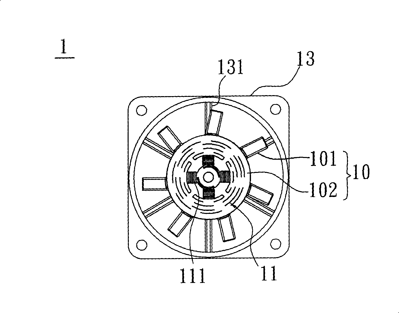
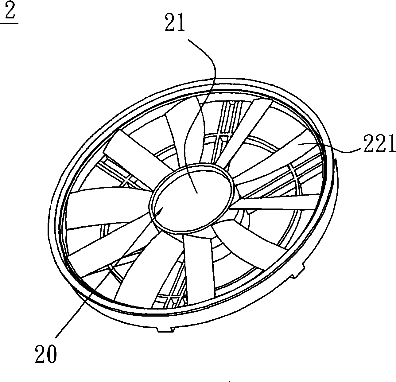
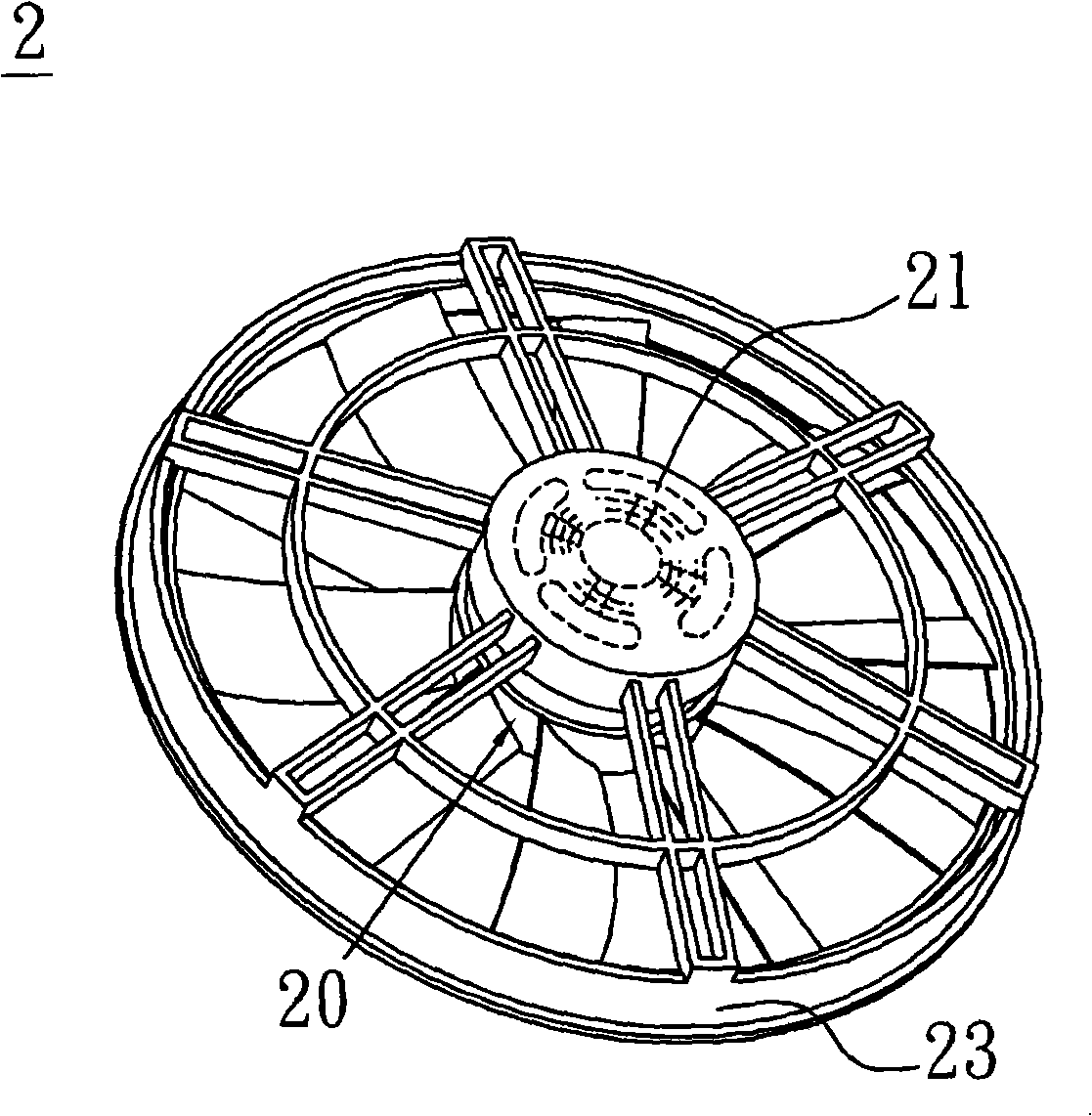
[0036] Please refer to Figure 2A and Figure 2B , which are front and back schematic diagrams of a fan according to a preferred embodiment of the present invention. A fan 2 according to a preferred embodiment of the present invention includes an impeller 20 , a motor 21 , and a fan frame 23 . Both the impeller 20 and the motor 21 are accommodated in the fan frame 23 , and the motor 21 is connected to drive the impeller 20 to rotate. The fan 2 in this embodiment is an axial fan, but it is not limited thereto, and of course it can also be a centrifugal fan.

[0037] Please also refer to Figure 2A and Figure 2C , Figure 2C for Figure 2A Schematic diagram of the middle impeller. The impeller 20 includes a hub 21 and an odd number of fan blad...


PUM


Abstract

The invention discloses a fan. The fan comprises an impeller, a motor and a fan frame. The impeller and the motor are received in the fan frame; the motor is connected with the impeller and drives the impeller to rotate, wherein, the impeller is provided with a hub and odd number of fan blade sets which are annularly arranged on the periphery of the hub; each fan blade set is respectively provided with a plurality of fan blades; and the fan blades in each fan blade set are the same or different with each other.

Description

technical field [0001] The invention relates to a fan and its impeller, in particular to a fan with an odd number of blade sets and its impeller. Background technique [0002] With the development of electronic products towards high performance, high frequency, high speed and thinner and thinner, the heating temperature of electronic products is often higher and higher, which is prone to unstable operation and affects product reliability. Therefore, heat dissipation has It has become one of the important topics in the research and development of electronic products. [0003] It is a common structural setting to use a fan as a cooling device, please refer to figure 1 , which is a schematic diagram of a conventional fan. The conventional fan 1 includes an impeller 10 , a motor 11 and a fan frame 13 . Both the impeller 10 and the motor 11 are accommodated in the fan frame 13 , and the impeller 10 is composed of a plurality of fan blades 101 and a hub 102 , and the fan blades...

Claims


Application Information

Patent Timeline
Patent Type & Authority Applications(China)
IPC IPC(8): F04D29/38F04D25/06
Inventor 篮重凯陈弘琪林丽真
Owner DELTA ELECTRONICS INC
Why Eureka
Try Eureka