Ring shell and tube type heat exchanger possessing commutation function

A heat exchanger and annular tube technology, which is applied in the field of heat exchange devices and annular shell-and-tube heat exchangers, can solve the problems of destroying the performance of the temperature field, and the constant temperature tank cannot be used continuously, so as to improve the performance of the temperature field and facilitate the internal uniformity. The effect of heat exchange and promotion of horizontal stirring force

Inactive Publication Date: 2008-10-15
BEIHANG UNIV
View PDF0 Cites 7 Cited by
  • Summary
  • Abstract
  • Description
  • Claims
  • Application Information

AI Technical Summary

Problems solved by technology

[0004] The purpose of the present invention is to provide an annular shell-and-tube heat exchanger with a rectification function that can be placed in a constant temperature liquid flow field. Advantageous; the constant temperature liquid input pipeline of the heat exchanger can accelerate the horizontal stirring of the liquid in the constant temperature tank, and improve the temperature field performance of the constant temperature tank; the heat exchange of the fluid inside and outside the tube bundle is uniform, and then the temperature control accuracy of the medium in the tube bundle is improved to solve the problem according to the existing technology. If the designed heat exchanger is directly placed in the constant temperature bath, it will destroy its temperature field performance, and even cause the problem that the constant temperature bath cannot continue to be used in this case

Method used


Image

  • Ring shell and tube type heat exchanger possessing commutation function
  • Ring shell and tube type heat exchanger possessing commutation function
  • Ring shell and tube type heat exchanger possessing commutation function

Examples


Embodiment Construction

[0029] The technical solutions of the present invention will be further described below in conjunction with the accompanying drawings and embodiments.

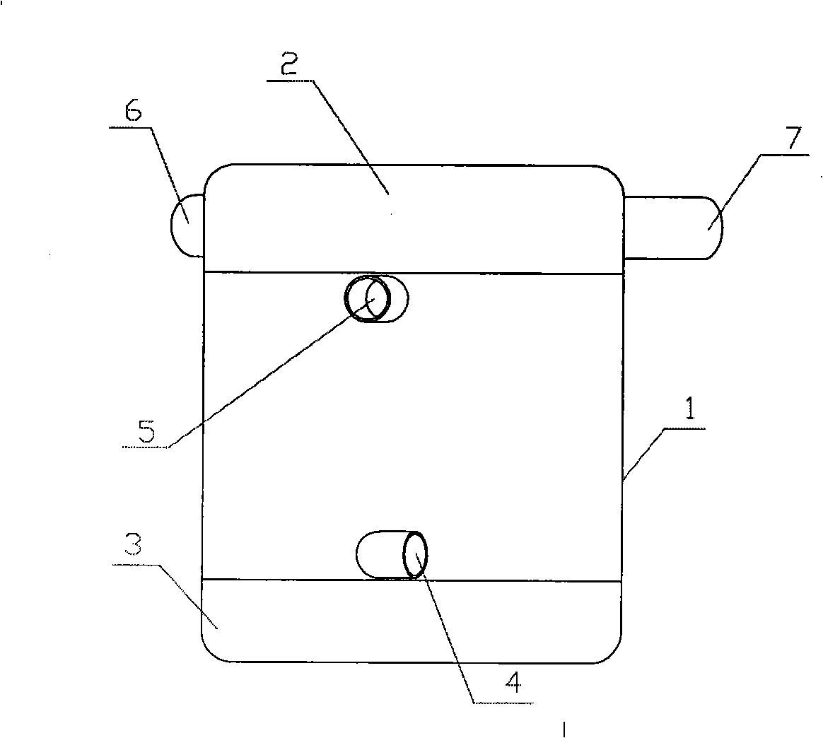
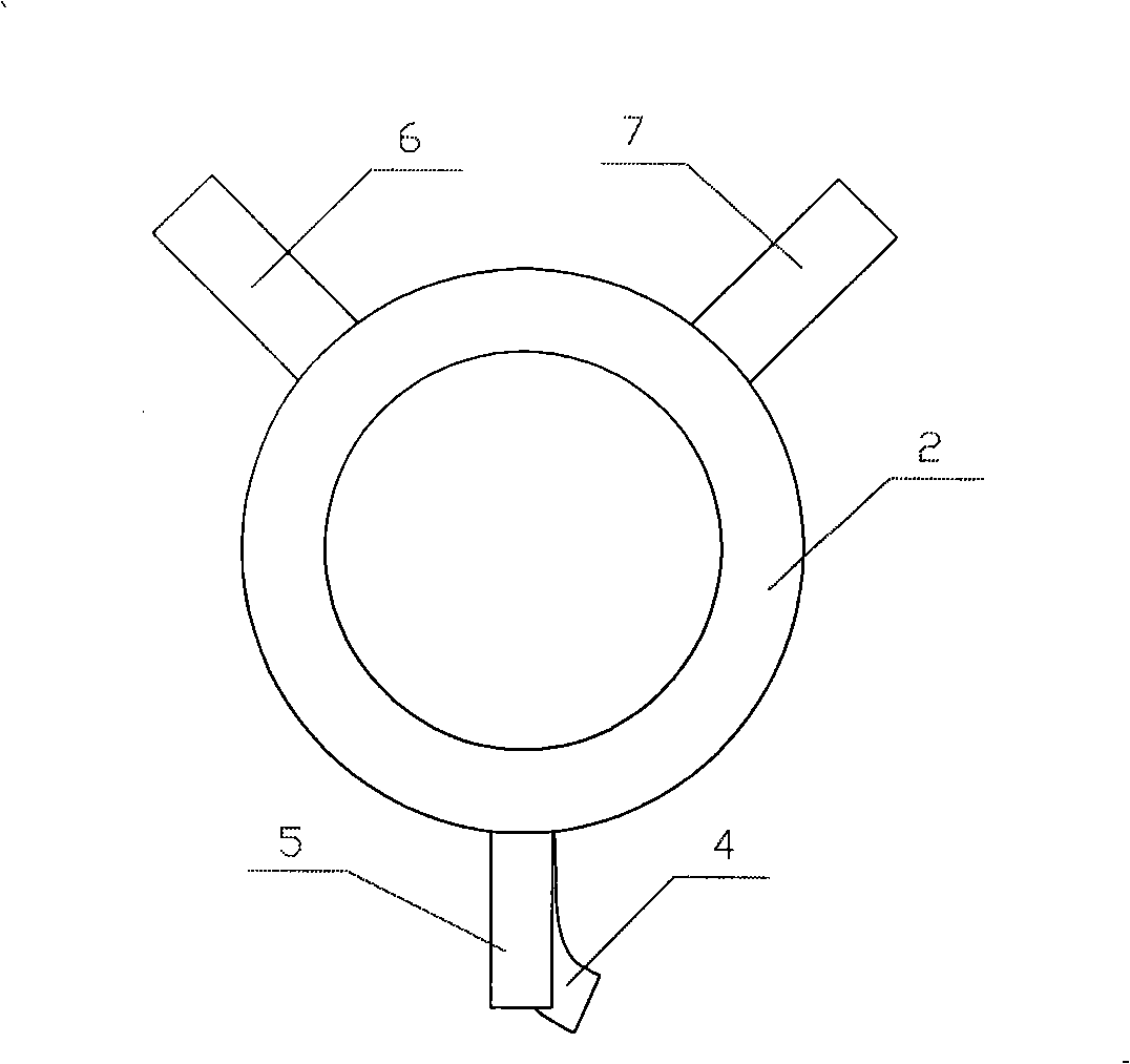
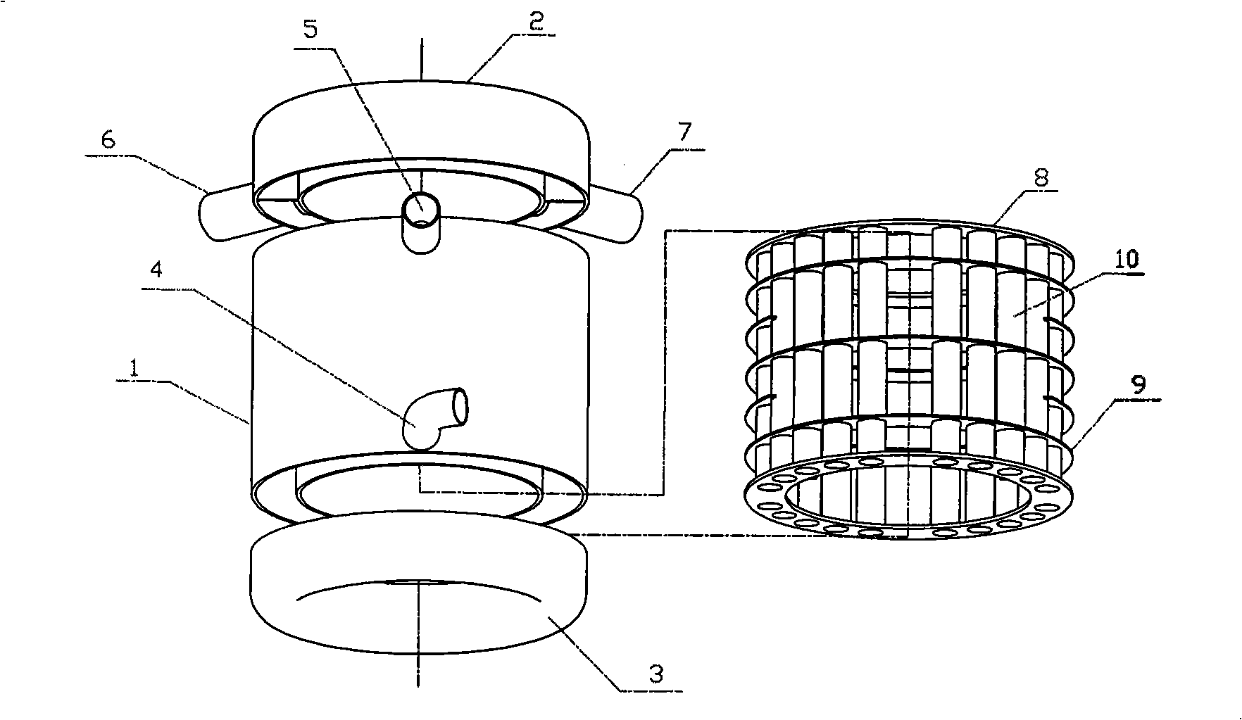
[0030] Please refer to Figure 1 to Image 6 , the present invention is a ring-shaped shell-and-tube heat exchanger with a rectification function, which is a ring-shaped vertical structure as a whole, and the interior is hollow. 1. Constant temperature liquid input pipeline 4, constant temperature liquid output pipeline 5, heat exchange medium input pipeline 6, heat exchange medium output pipeline 7 and core body. The housing 1 is a hollow barrel-shaped interlayer structure. The outer lower part of the housing 1 has a constant temperature liquid input pipe 4 that gradually transitions from a straight line to a circular arc and extends horizontally. Constant temperature liquid output pipeline 5. The upper cover body 2 is an annular groove-shaped structure matched with the shell, with a separator 11 for controlling the number o...


PUM


Abstract

The invention provides a ring-shaped shell-and-tube heat exchanger capable of commutating, consisting of a housing, an upper cover body, a lower cover body, a clapboard and a core body, wherein, the whole heat exchanger has a ring-shaped vertical structure and a hollow inner part; the housing has a hollow barrel-shaped interlayer structure, a constant temperature liquid input pipeline is positioned at the lower part of the outside of the housing and is transited gradually to a circular arc extending out horizontally along a straight line, the upper part of the outer side of the housing is provided with a linear constant temperature liquid output pipeline extending out horizontally; a ring-shaped groove structure matched by the upper cover body and the housing is provided the clapboard for controlling the number of tube passes inside, the outer side is provided with a heat exchanging medium input pipeline and a heat exchange output pipeline; the lower cover body has the same shape as the lower cover body, the inside is provided with the clapboard; the core body comprises a pipe, traverse baffles and pipe supports; the traverse baffles are sleeved on the pipe in a way of opposite one another and crisscross, the vertical length of the pipe is divided equally, the top part and the bottom part of the pipe are provided with the pipe supports; the core body is arranged inside the interlayer of the housing, the pipe supports and the edge of the housing are welded into a whole and are welded with the upper cover body and the lower cover body.

Description

(1) Technical field: [0001] The invention relates to an annular shell-and-tube heat exchanger with a rectification function, especially a shell-and-tube heat exchanger placed in a constant temperature liquid flow field. It belongs to heat exchange device. (two) background technology: [0002] Traditional shell and tube heat exchangers such as Figure 7 As shown, it is a cylinder-like body as a whole, consisting of a housing 1', an upper cover 2', a lower cover 3', and a core. The inside of the upper cover body 2' is separated by a partition 11', and the number of partitions determines the number of tube passes. Figure 7 Shown is a two-tube pass heat exchanger. The heat exchange medium enters part of the tube bundles from the heat exchange medium input pipe 6', and after reaching the bottom of the heat exchanger, passes through the lower cover to divert the flow to change its direction, flows upward into the remaining tube bundles, and flows out of the heat exchange medium ...

Claims


Application Information

Patent Timeline
Patent Type & Authority Applications(China)
IPC IPC(8): F28D7/10F28D7/16
Inventor 孟晓风张卫军杨明
Owner BEIHANG UNIV
Why Eureka
Try Eureka