
Controlled stamper machine

A stamping machine and stamping technology, applied in printing, electrical program control, program control in sequence/logic controllers, etc., can solve the problems of inability to use steel stamps, slow printing speed, and high cost, and achieve fast stamping speed, Simple structure and low cost

Inactive Publication Date: 2008-10-22
杭州东信银星金融设备有限公司
View PDF5 Cites 16 Cited by
  • Summary
  • Abstract
  • Description
  • Claims
  • Application Information

AI Technical Summary

Problems solved by technology

The latter is the implementation device in the former scheme, and its main content is driven by a closed casing with a paper inlet and outlet door, a paper tray assembly, a stamp assembly, a stamp mounting frame, and a stamp horizontally mounted on the inner frame of the closed casing. device, seal up and down driving device, imaging device and control circuit board, the technical solution of the combination of the above invention and utility model patent has undoubtedly played a positive role in the control and automation of stamping, but the shortcomings are (1) complicated mechanism , bulky
(2) High cost
(3) Slow printing speed and low efficiency
(4) Steel stamps cannot be used, (5) Cannot replace special stamping requirements
For users with many outlets and high real-time processing requirements, such as banks and securities companies, it is difficult to use

Method used


Image

  • Controlled stamper machine
  • Controlled stamper machine
  • Controlled stamper machine

Examples


Embodiment Construction

[0033] Referring to the attached picture:

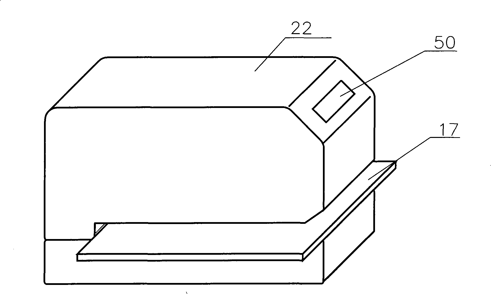
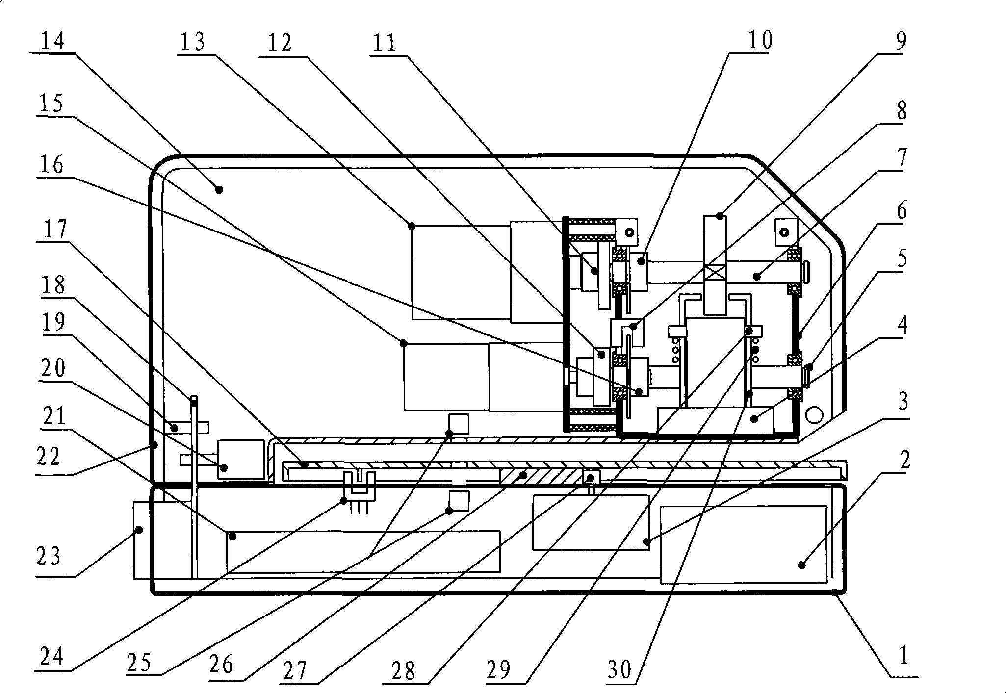
[0034] Controlled seal of the present invention comprises a totally enclosed cabinet (casing is made up of upper cover 1, base 2,) has in the cabinet:

[0035] A control main board 21 containing a central processing unit, which has an interface connected to an external PC;

[0036] The electronic door lock 23 of the cabinet, the door lock 23 includes an electromagnet 20 that controls the door lock switch, and the electromagnet 20 is controlled by the central processing unit 21;

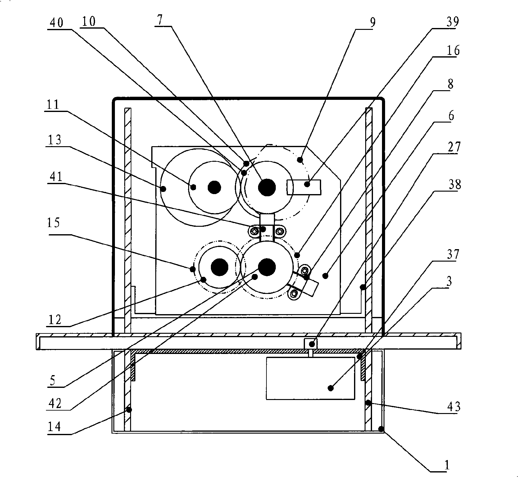
[0037] A frame is made up of side plates 14,43 support plates 37,38, and a seal movement is installed on the frame;

[0038] There is a stamp assembly driving mechanism controlled by the central processing unit 21 on the frame;

[0039] A ink-on mechanism controlled by the central processing unit 21;

[0040] A file input mechanism controlled by the central processing unit 21;

[0041] The motor 15 and the gear transmission mechanism that provide power f...


PUM


Abstract

A controlled seal machine comprises a totally enclosed chassis which is provided with a control mainboard comprising a CPU; the CPU is provided with an interface for connecting an external PC; an electronic door lock of the chassis comprises an electromagnet which controls a switch of the door lock and is controlled by the CPU; a frame is provided with a seal component and a seal component drive mechanism controlled by the CPU; a squeegee oil feeding mechanism is controlled by the CPU; a document input mechanism is controlled by the CPU; the controlled seal machine also comprises a motor providing power for the seal component drive mechanism, the squeegee oil feeding mechanism and the document input mechanism as well as a gear transmission mechanism.

Description

technical field [0001] The invention relates to a device that must receive instructions from an authorized person through a communication port to realize the operation of stamping a device consisting of a stamp assembly, a cam drive mechanism, an ink supply mechanism, a mobile platform, a motor, a control panel, and a frame shell. machine. This machine is used in the management of important seals of banks, insurance, securities and other enterprises and institutions. It belongs to automatic office equipment. Background technique [0002] The traditional seal is to be kept by a designated person, and the applicant for the use of the seal shall apply for the seal with the approval of the authorized person, and the seal custodian shall perform the seal. This method relies on the system, the moral character and work responsibility behavior of the stamp operator to ensure the safety of the seal operation. In real life, stamping favors, embezzling stamps, and stamping privately...

Claims


Application Information

Patent Timeline
Patent Type & Authority Applications(China)
IPC IPC(8): B41K3/00B41K3/62G05B19/04
Inventor 徐平
Owner 杭州东信银星金融设备有限公司
Learn More