Numerical control machine heat error compensation temperature point position determination method

A technology of numerical control machine tools and temperature compensation, which is applied in the direction of measuring devices, testing of machine/structural components, instruments, etc., and can solve the problems of time and sensor waste

Inactive Publication Date: 2008-10-22
UNIV OF SHANGHAI FOR SCI & TECH +1
View PDF0 Cites 31 Cited by
  • Summary
  • Abstract
  • Description
  • Claims
  • Application Information

AI Technical Summary

Problems solved by technology

Determining temperature measurement points based on experience and trial and error leads to a lot of wasted time and sensors that are not used in the final error modeling

Method used


Image

  • Numerical control machine heat error compensation temperature point position determination method
  • Numerical control machine heat error compensation temperature point position determination method
  • Numerical control machine heat error compensation temperature point position determination method

Examples


Embodiment Construction

[0025] The present invention will be further described below in conjunction with the accompanying drawings and embodiments.

[0026] A method for determining the position of a measuring point of a thermal error compensation temperature sensor of a numerically controlled machine tool, the specific steps of which are:

[0027] (1) Finite element analysis of thermal characteristics of CNC machine tools

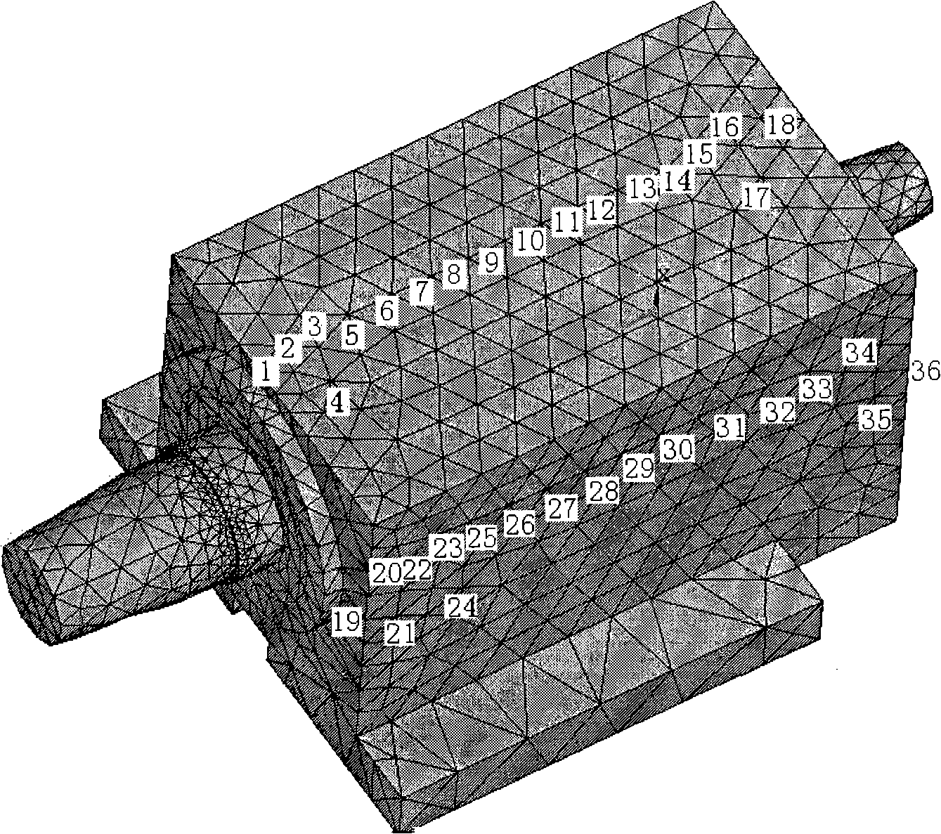
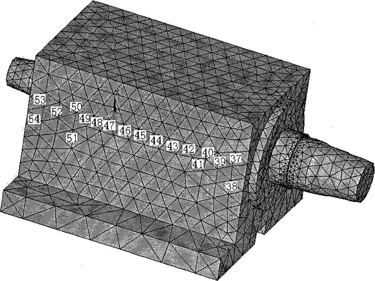
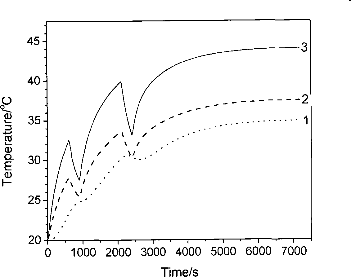
[0028] Establish the finite element model of the research object, determine the heat source and boundary conditions, and use the finite element analysis software to calculate its transient temperature field T(t) and thermal deformation Y(t);

[0029] Let the undetermined position of the temperature measurement point on the machine tool be X: {x 1 , x 2 ,...,x n}, obtained by finite element analysis: ①The variation of temperature at these locations with time is T: {T 1 (t), T 2 (t),...,T n (t)}, ② Machine tool deformation: the thermal deformation of the relative position cha...


PUM


Abstract

The invention relates to a method for determining the position of a measuring point of a temperature sensor for thermal error compensation of a numerical control machine, comprising the following steps of: 1. analyzing a finite element of thermal property of the numerical control machine; 2. calculating mutual information quantity of numerical control machine deformation provided by a measuring point temperature value Ti (t) according to informationism; 3. calculating mutual information quantity of numerical control machine deformation Y(t) provided by a combination of m temperature measuring points. With the method, the problem of optimized calculation for determining the position of the temperature sensor during the process of thermal error modeling for the numerical control machine can be solved. The method uses the method of numerical calculation to replace the prior experimental method, and can realize prediction of thermal deformation of the numerical control machine with the least temperature sensors, thereby effectively reducing the number of temperature measuring points of the numerical control machine, saving time and cost, and improving the validity of the thermal error compensation model of the numerical control machine.

Description

technical field [0001] The invention relates to a method for measuring and compensating the thermal deformation of a machine tool in the cutting process of a precision machine tool. Background technique [0002] In the cutting process of precision machine tools, the heat source has a great influence on the machining accuracy. To improve the machining accuracy of the workpiece, it is necessary to conduct quantitative research on the thermal deformation of the workpiece and the thermal deformation of the machine tool, and make reasonable control and compensation during the processing. The measurement and compensation of the thermal error of the machine tool generally needs to be based on the measurement of the thermal error of the machine tool, by analyzing the relationship between the measured values ​​of the temperature sensors at different positions of the machine tool and the thermal deformation of the machine tool, establishing a thermal error model of the CNC machine tool...

Claims


Application Information

Patent Timeline
Patent Type & Authority Applications(China)
IPC IPC(8): G01M19/00G01M99/00
Inventor 李郝林应杏娟姚俊
Owner UNIV OF SHANGHAI FOR SCI & TECH
Why Eureka
Try Eureka