

Optical position detection device and electronic equipment
A detection device and a technology for detecting light, which are applied in measuring devices, line-of-sight measurement, distance measurement, etc., can solve problems such as weak signal strength, expensive devices, and poor detection accuracy, and achieve the effect of expanding the scope of application
Inactive Publication Date: 2008-10-22
SHARP KK
View PDF3 Cites 46 Cited by
- Summary
- Abstract
- Description
- Claims
- Application Information
AI Technical Summary
Problems solved by technology
If an analog signal is transmitted, the greater the distance, the greater the noise component superimposed on the signal line, and there is a problem that the position detection accuracy deteriorates
Also, position detectors become expensive if A / D converters are included in each receiver
In addition, the signal strength detected by the receiver is very weak, so it is necessary to amplify the signal near the receiver, and a signal processing circuit equivalent to the number of receivers is required, and a power supply system is also required to wind a long distance for the signal processing circuit
Method used
View moreImage
Smart ImageViewing Examples

Examples
no. 1 approach
no. 2 approach
no. 3 approach
Login to View More PUM
 Abstract
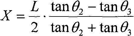
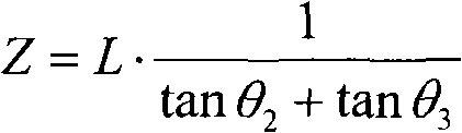
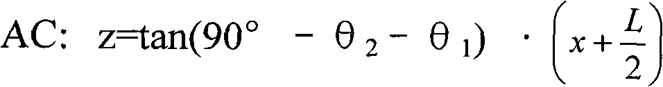
This invention provides an optical position detection device capable of detecting the position of a light source and with low price. An emission system is based on a certain distance between a second light source (12) and a third light source (13); a signal light (R2) from the second light source (12) is corresponded to an incident angle (Theta 2) of the emission system (1); a signal light (R3) from the third light source (13) is corresponded to an incident angle (Theta 3) of the emission system (1);the detection emission system (1) is corresponded to the position of a receiving system (2).
Description
Optical position detection device and electronic equipment technical field The invention relates to a detection device for determining the position of emitted light, which uses signal light emitted by a remote controller to determine the position of the remote controller. In addition, the present invention relates to electronic equipment such as air conditioners, video equipment, audio equipment, and cameras, which include the above optical position detection device. Background technique Conventionally, various light angle detection devices for detecting the position of a light source such as a remote controller have been proposed. The light-receiving unit generally arranges two photodiodes adjacent to each other, or uses PSD (Position SensitiveDevice, position sensing device), and properly arranges a light-shielding material on the light-receiving surface, and generates the light-shielding material based on the incident angle of light. To detect the difference between t...
Claims
Login to View More Application Information
Patent Timeline
 Patent Type & AuthorityApplications(China)
IPC IPC(8): G01S11/00
CPCG01C3/06
Inventor和田秀夫
OwnerSHARP KK