Multi-speed ring oscillator

A ring oscillator, oscillator technology, applied in electrical pulse generator circuits, logic circuits to generate pulses, pulse technology, etc., can solve problems such as exceeding inverter gate delays

Inactive Publication Date: 2008-10-22
TECH PROPERTIES
View PDF3 Cites 1 Cited by
  • Summary
  • Abstract
  • Description
  • Claims
  • Application Information

AI Technical Summary

Problems solved by technology

[0006] In current semiconductor technology for embedded CMOS microprocessor systems, the ability to use EDA tools for ring oscillator design and layout is desirable because embedded CMOS microprocess

Method used


Image

  • Multi-speed ring oscillator
  • Multi-speed ring oscillator

Examples


Embodiment Construction

[0015] The following description is provided to enable any person skilled in the art to make and use the invention, and is provided in a specific application context. Various modifications may be made to the embodiments without departing from the spirit and scope of the invention, and the general principles defined herein may be applied to these and other embodiments and applications. The present invention is thus not intended to be limited to the illustrated embodiments and applications, but is to be accorded the widest scope consistent with the principles, features and teachings disclosed herein.

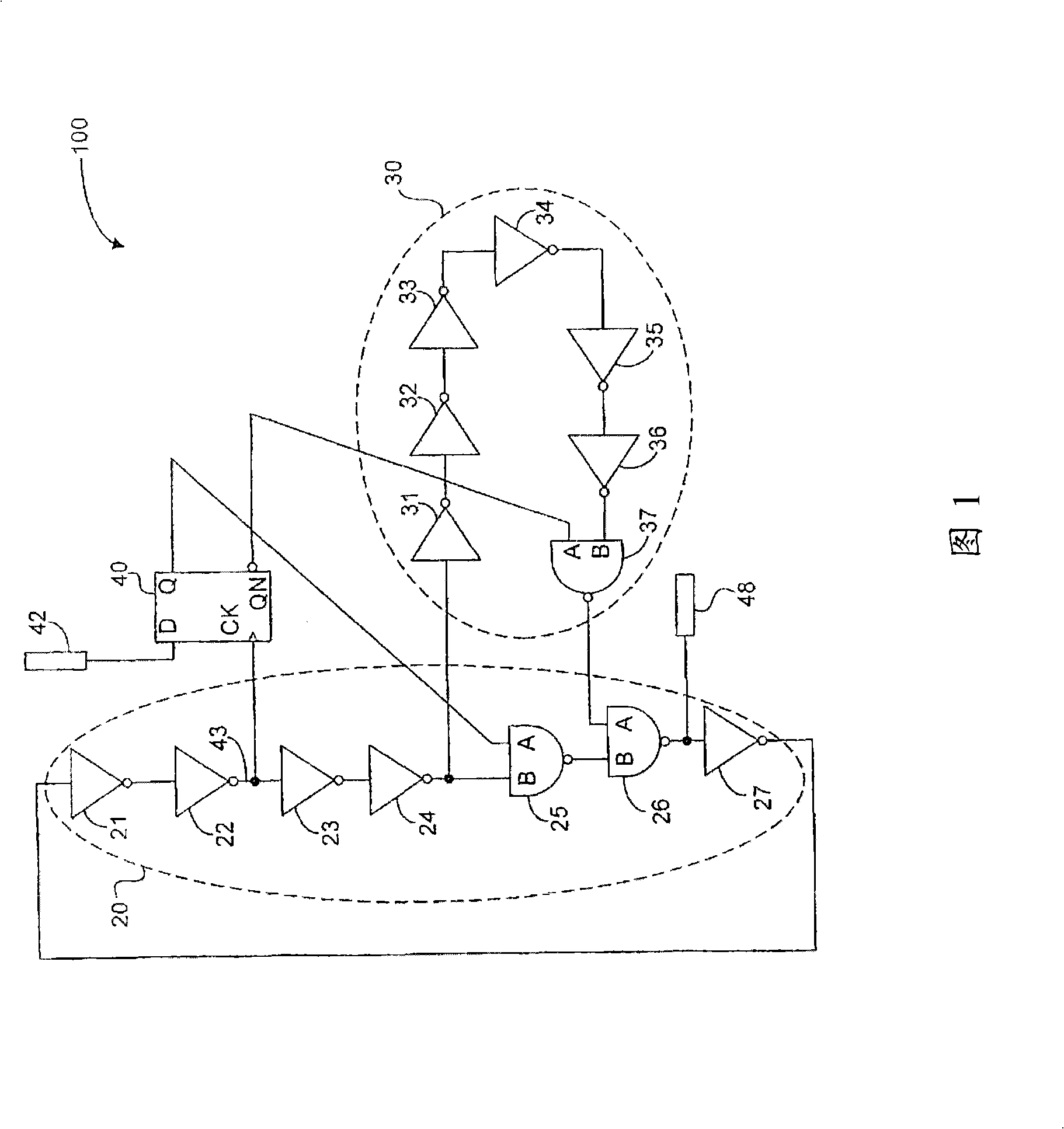
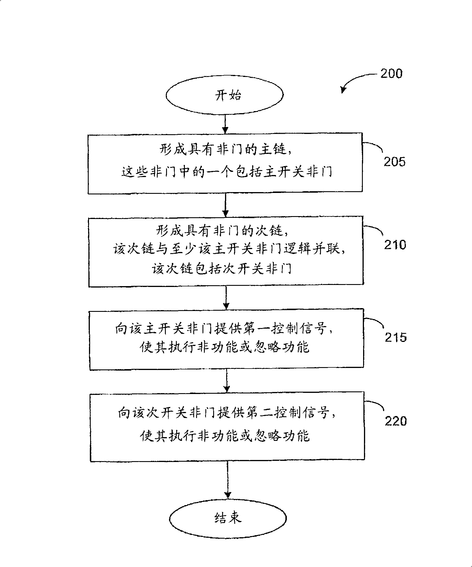
[0016] According to one embodiment, the present invention provides a multi-speed, frequency-controllable ring oscillator that can be used for clocking an embedded complementary metal-oxide-semiconductor (CMOS) microprocessor system. In one embodiment, the ring oscillator is entirely digital and includes a primary chain with NOT gates and one or more secondary chains with NOT gates...


PUM


Abstract

An annular oscillator comprises a control circuit for receiving the frequency selecting signal; the frequency selecting signal can be operated as processing the selection in at least two different annular oscillator frequencies; the control circuit uses the control signal to generate a first control signal and a second control signal; a main chain with the odd number series-connecting connections, the main chain comprises a main switch non-gate; the main switch non-gate is responding to the first control signal which can be operated as implementing the logical non-function or ignoring function for the first oscillating inputting signal to output the first outputting signal; and a slave chain series-connecting non-gate; the slave chain is collaterally connected to the main switch non-gate of the main china at least; the slave chain comprises a slave switch non-gate; the slave switch non-gate is responding to the second control signal which can be operated as implementing the logical non-function or ignoring function for the second oscillating inputting signal to output the second outputting signal.

Description

technical field [0001] This invention relates generally to digital circuits and, more particularly, to multispeed ring oscillators. Background technique [0002] A ring oscillator is a device that includes an odd number of NOT gates, such as an inverter whose output voltage oscillates between logic high and logic low. The NOT gates of the traditional ring oscillator are connected in a circular chain, so that the output voltage of the last NOT gate among the odd number of NOT gates is fed back as the input of the first NOT gate. Since the chain includes an odd number of NOT gates, the logic voltage leaving the last NOT gate is the logical NOT of the input voltage previously entering the first NOT gate. Therefore, the output voltage of each NOT gate in the loop oscillates. Since the output voltage of the last NOT gate is judged to reach the first NOT gate a finite amount of time after the previous input voltage, each NOT gate oscillates at a predictable frequency. [0003] ...

Claims


Application Information

Patent Timeline
IPC IPC(8): H03K3/03
CPCH03K3/0315H03K3/03
Inventor 朗尼·C·戈夫
Owner TECH PROPERTIES
Why Eureka
Try Eureka