Dark corner eliminating method and system in digital image

A technology of image center and imaging system, applied in image communication, components of TV system, solid image signal generator, etc., can solve problems such as image brightness fading

Inactive Publication Date: 2008-10-22
NOKIA CORP
View PDF0 Cites 21 Cited by
  • Summary
  • Abstract
  • Description
  • Claims
  • Application Information

AI Technical Summary

Problems solved by technology

However, camera lenses in small portable devices such as mobile phones are usually not part of a complex lens system, and the image brightness in the image boundary area is likely to suffer significant degradation

Method used


Image

  • Dark corner eliminating method and system in digital image
  • Dark corner eliminating method and system in digital image
  • Dark corner eliminating method and system in digital image

Examples


Embodiment Construction

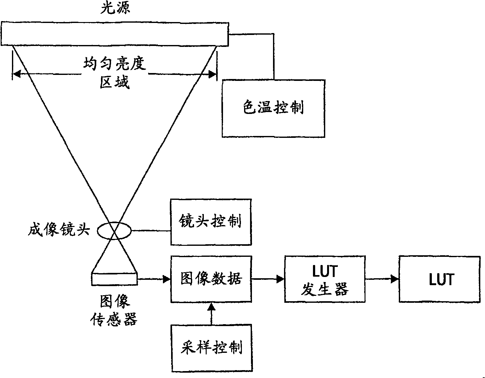
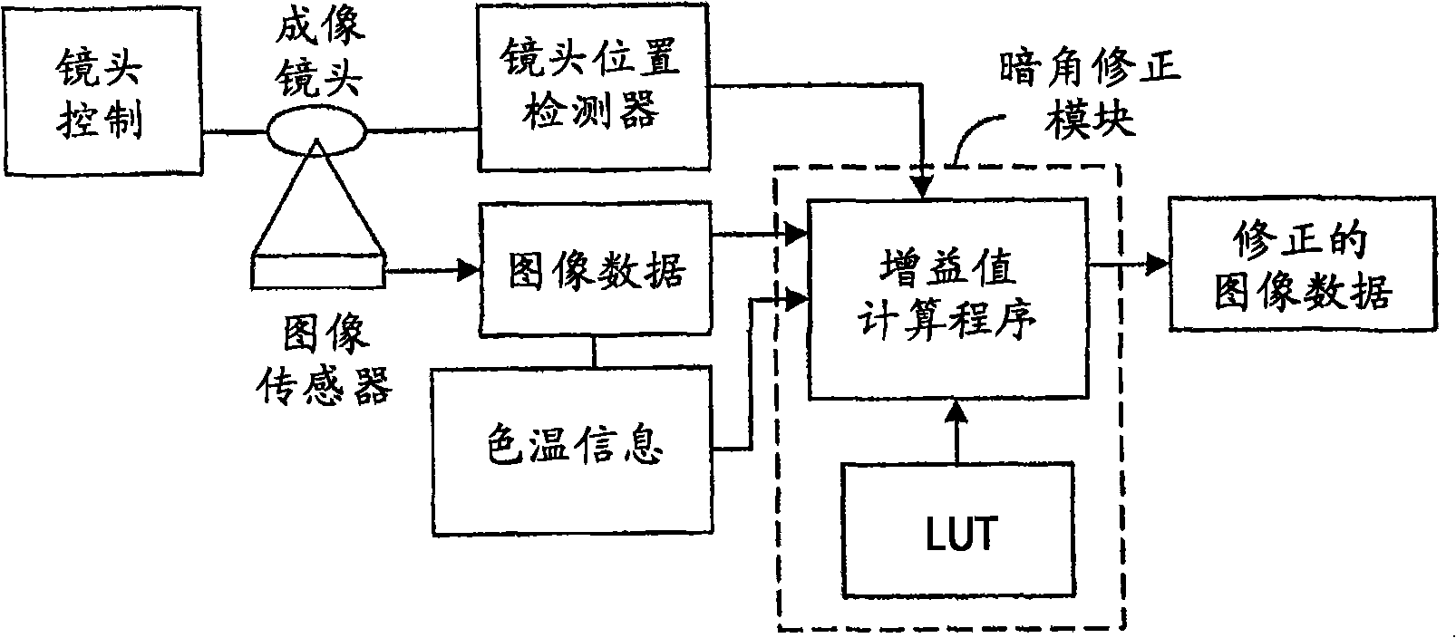
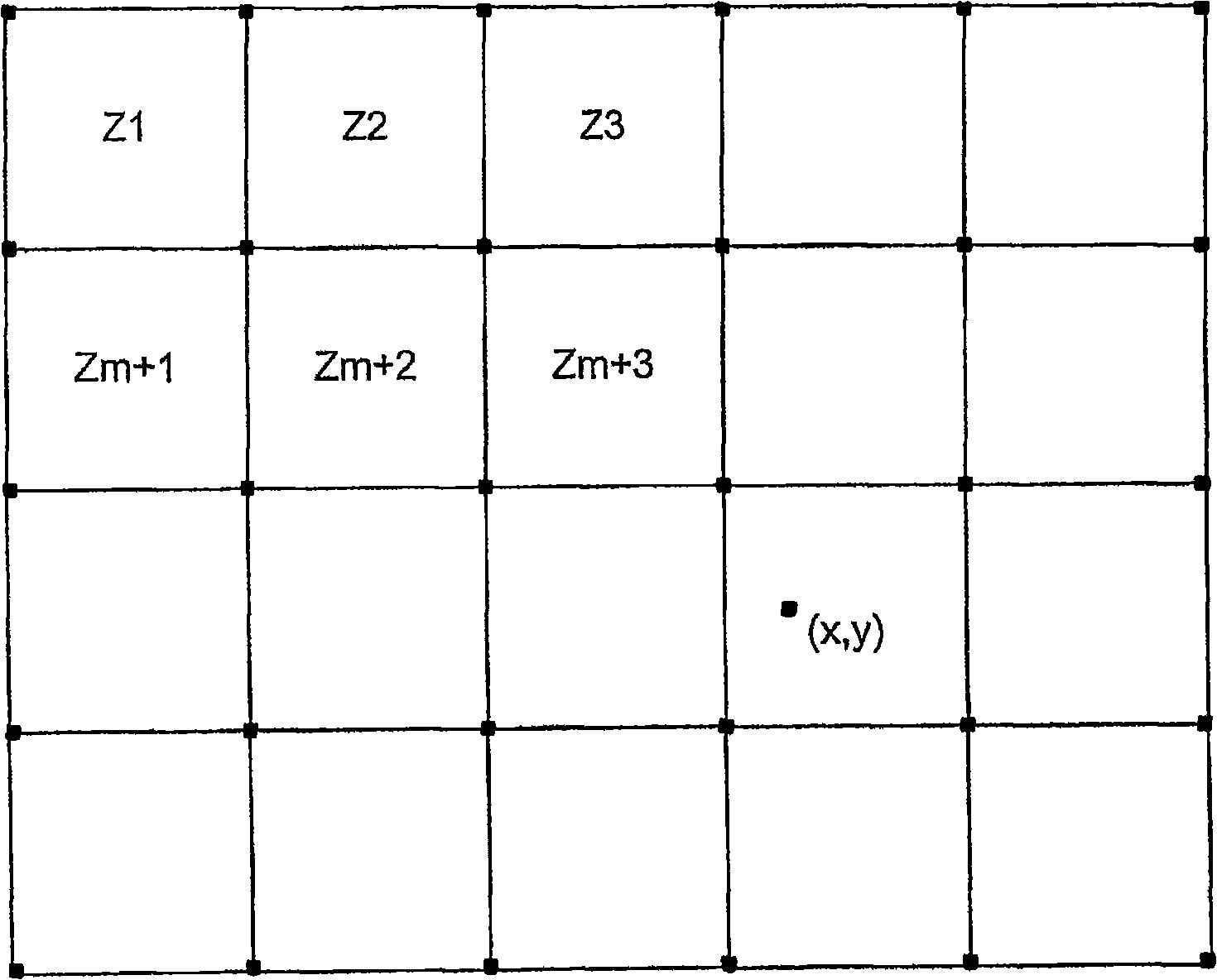
[0014] The present invention uses one or more look-up tables for vignetting correction. Instead of generating a lookup table containing correction factors for each pixel in the image area, the present invention samples the vignetting effect on the test image at a plurality of locations distributed on a sparse grid spread over the image area, And a lookup table is generated according to the gain values ​​at the sampling grid locations. Effectively, the image area is divided into image partitions, each partition being bounded by four grid locations. Thus, the modified gain for each pixel within the partition is computed at run time by interpolating the gain value from the modified gain values ​​at those four grid locations, taking into account the pixel to each of those grids grid distance.

[0015] The present invention involves two general level stages:

[0016] 1) Generate a reference look-up table (LUT) based on a suitable test image captured by such an image sensor that ...


PUM


Abstract

An imaging system having one or more look-up tables to compensate for vignetting effect on an image sensor by a lens. An image of a test target formed by the lens is captured by the image sensor and sampling is carried out at discrete locations distributed on a sparse grid throughout the image area. The look-up table is generated according to gain values at sampling grid locations. Two or more look-up tables may be generated for different color temperatures and different lens positions. Image area is effectively divided into a plurality of image zones, each zone defined by four grid locations. The correction gain for each pixel within a zone is calculated in run time by interpolating a gain value on the basis of the correction gain values at those four grid locations, taken into account the distance of the pixel from each of those grid locations.

Description

technical field [0001] The present invention relates generally to digital camera imaging, and more particularly to the processing of raw imaging data, such as Bayer data. Background technique [0002] It is known in the art that images formed behind a camera lens always suffer from non-uniform brightness problems (known as falling-off and vignetting). Vignetting means the darkening of the corners and borders of the image relative to the center of the image. According to a law of optics known as the fourth law of cosines, when a single lens is used to form an image, the amount of light reaching the focal plane of the lens away from the optical axis decreases. By combining lens systems, this fading can be significantly reduced or substantially eliminated. However, camera lenses in small portable devices such as mobile phones are usually not part of complex lens systems, and the image brightness in the image boundary area is likely to suffer significant degradation. The vign...

Claims


Application Information

Patent Timeline
Patent Type & Authority Applications(China)
IPC IPC(8): H04N5/243H04N5/217H04N5/357
CPCH04N5/3572H04N9/045H04N25/61H04N23/84
Inventor J·尼克卡南O·卡勒沃
Owner NOKIA CORP
Why Eureka
Try Eureka