Gantry planning and milling transmission box

A gearbox, planing and milling technology, applied in the field of machinery, can solve the problems of complex DC control, high power consumption of the motor, and high cost, and achieve the effects of huge economic and social benefits, high power consumption, and high cost

Inactive Publication Date: 2008-10-29
宋保通
View PDF0 Cites 2 Cited by
  • Summary
  • Abstract
  • Description
  • Claims
  • Application Information

AI Technical Summary

Problems solved by technology

[0003] In view of the above situation, in order to overcome the shortcomings of the existing gantry planer, the purpose of the present invention is to provide a gantry planer milling gearbox, which can effectively solve the problem that the gantry planer is both planing and milling, saving money and energy. The technical solution is , the left side of the box is equipped with a hydraulic non-stop clutch. The hydraulic non-stop clutch is connected to the differential speed reducer through the clutch gear. The output shaft of the differential speed reducer is installed on the coupling shaft of the power wheel of the planer at the outer end of the box. The reducer is equipped with an output gear on the output shaft in the box, and the transmission shaft is equipped with a passive gear, a first fork gear, a second fork wheel and a rotating gear in sequence from left to right. The first fork gear is the same as the first fork gear. The fork is connected, the second fork wheel is connected with the second fork, the first fork gear is clutched with the clutch gear, the second fork wheel is clutched with the transmission gear, there is a third fork on the motor gear, and the motor gear is in the same box The gears of the milling reducer in the lower part of the body are clutched, and the output shaft of the milling reducer is equipped with an output wheel, which meshes with the rotating gear on the drive shaft through the wheel; the hydraulic non-stop clutch brakes the differential reducer on the left to decelerate the feed, hydraulic pressure The non-stop clutch brakes on the right side, the differential reducer and the clutch gear and transmission gear output fast return at the same speed, and the differential reducer can brake on the left through the braking hydraulic non-stop clutch when not stopping, and the differential reducer outputs at low speed. When the brake is not stopped, the right brake of the hydraulic non-stop clutch can drive the differential reducer with the clutch gear and the transmission gear to return quickly at the same speed
[0004] The present invention has dual functions of milling and planing, the energy consumption can be reduced by half (50%), the AC control is convenient and simple, it completely changes the problems that the planer cannot mill, the power consumption of the motor is large, the DC control is complicated and the cost is high, and it is a unique solution in the planer equipment. The great creation solves the technical problem that people have long hoped to solve a planer that can plan and mill, and has huge economic and social benefits

Method used


Image

  • Gantry planning and milling transmission box

Examples


Embodiment Construction

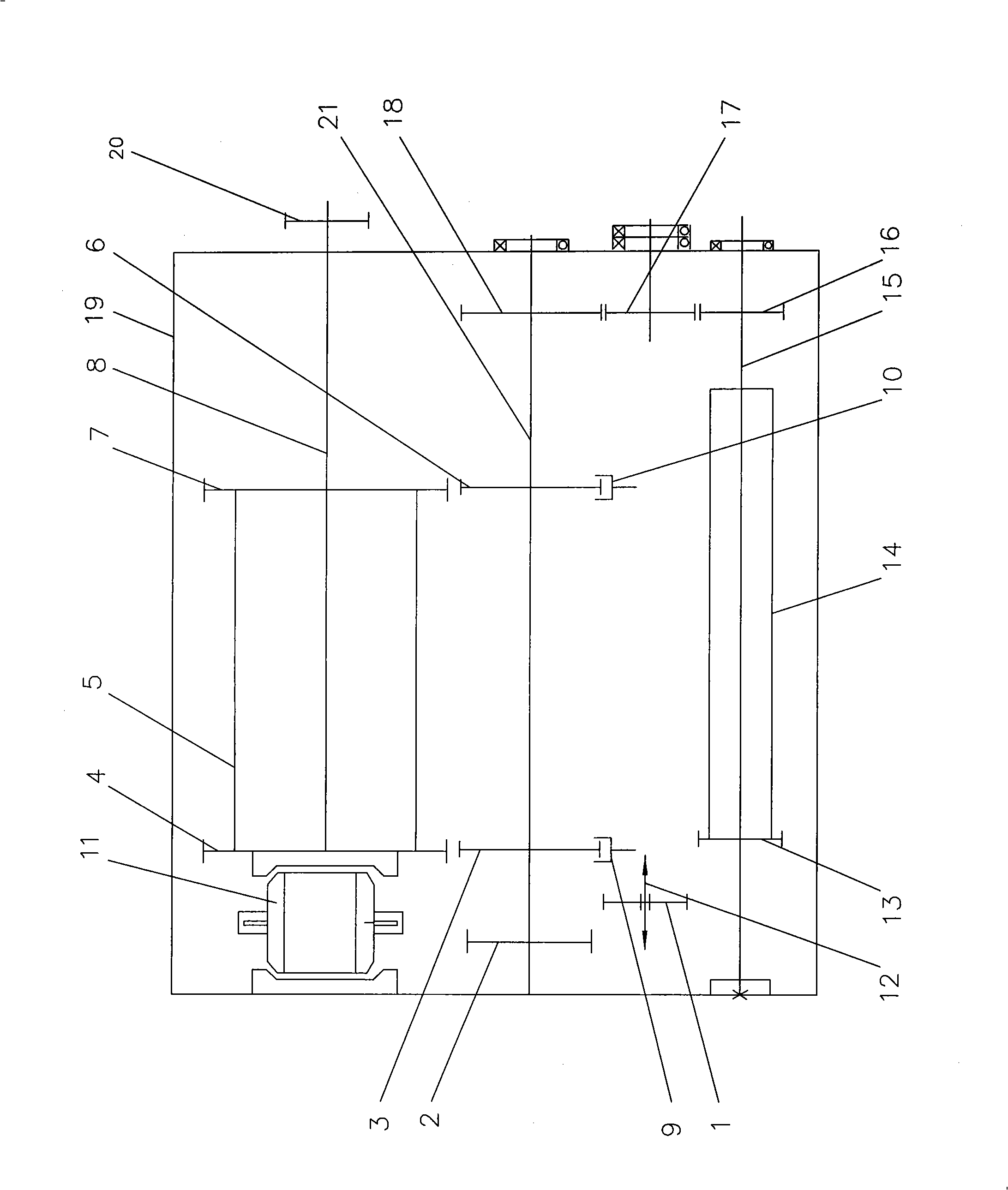
[0006] The specific implementation manners of the present invention will be described in detail below in conjunction with the accompanying drawings.

[0007] Provided by accompanying drawing, hydraulic non-stop clutch 11 is housed in casing 19 left sides of the present invention, hydraulic non-stop clutch 11 links to each other with differential speed reducer 5 through clutch gear 4, and the output shaft 8 of differential speed reducer 5 is in casing 19 The outer end of the planer is mounted on the coupling shaft of the planer power wheel 20, the differential speed reducer 5 is equipped with a transmission gear 7 on the output shaft 8 in the box body 19, and the transmission shaft 21 is sequentially equipped with the driven gear 2, the first A fork gear 3, a second fork wheel 6 and a rotating gear 18, the first fork gear 3 is connected with the first fork 9, the second fork wheel 6 is connected with the second fork 10, the first fork gear 3 is clutched with the clutch gear 4, ...


PUM


Abstract

The invention relates to a transmission case of a gantry planer and realizes both planing and milling operations of a gantry planer with low cost and energy consumption. The transmission case has a structure as follows: a hydraulic non-stop clutch is arranged on the left side of a case body, the hydraulic non-stop clutch is connected with a differential speed reducer via a clutch gear, the output shaft of the differential speed reducer is mounted on the coupling shaft of a power wheel of the planer, an output gear is arranged on the output shaft of the differential speed reducer, the transmission shaft is provided thereon with, from the left to the right, a driven gear, a first shift fork gear, a second shift fork gear and a rotary gear, wherein, the first shift fork gear is connected with a first shift fork, the second shift fork gear is connected with a second shift fork, the first shift fork gear is coupled to the clutch gear, the second shift fork gear is coupled to the a driving gear, a third shift fork is arranged on a motor gear, the motor gear is coupled to the gear of a milling reducer which is positioned on the lower part of the case body, and the output wheel on the output shaft of the reducer engages with the rotary gear on the transmission shaft via a wheel. The transmission case realizes both planing and milling operations and has large economic and social benefits.

Description

1. Technical field [0001] The invention relates to the mechanical field, in particular to a gantry planer and milling gearbox. 2. Background technology [0002] Large-scale gantry planers are the most basic and necessary working machines in the machinery industry of all countries in the world, and are in great demand. Traditionally, the AC motor drives the DC generator to generate electricity, and the DC speed regulating motor drags the workbench to do slow linear cutting, and the empty car returns quickly, which results in low work efficiency. In this way, the 60kw DC speed regulating motor must be adjusted to a very low level during heavy cutting. The speed is only suitable for heavy cutting feed, and when the 60kw motor is adjusted to a very low speed, it is only equivalent to about 10kw power, and the power loss is very large. When the empty car returns, it returns at high speed and high power, which also wastes power energy. This kind of gantry planer, which consumes a...

Claims


Application Information

Patent Timeline
Patent Type & Authority Applications(China)
IPC IPC(8): F16H3/32F16H57/02B23Q15/013B23P23/02
Inventor 宋保通
Owner 宋保通
Why Eureka
Try Eureka