
Automatic regulation granulating mechanism

An automatic adjustment and granulation technology, applied in the field of granulation mechanism, can solve the problems of difficult manufacturing, difficult implementation, excessive contact force of cutter, etc., and achieve the effect of good product quality, easy maintenance and reliable operation

Inactive Publication Date: 2008-11-05
辽阳亿方造粒设备有限公司
View PDF2 Cites 2 Cited by
  • Summary
  • Abstract
  • Description
  • Claims
  • Application Information

AI Technical Summary

Problems solved by technology

Otherwise, the cutting edge with high contact pressure will cause greater wear and even break
However, due to installation errors and other reasons that are difficult to overcome, it is difficult to achieve this goal for the rigid pelletizing mechanism; The contact pressure between the cutting edge and the template is different
At the same time, when the contact pressure between the individual cutting edge and the template is too low, the cut particles will be tailed and the product quality will be affected.
[0003] U.S. Patent No. 6,793,473 provides a non-rigid pelletizing mechanism. However, due to the restraint of elastic parts, this solution needs to exert a large thrust on the non-rigid pelletizing mechanism. There is still a problem that the contact force of individual cutters is too large, resulting in These cutters are subject to greater wear
Chinese patent CN 2 2860772 provides another kind of non-rigid pelletizing mechanism, but this scheme has complex structure and is difficult to implement in the actual space
Japanese patent JP2003-326519 also provides a non-rigid pelletizing mechanism, but it is more difficult to manufacture and difficult to implement in the actual space.

Method used


Image

  • Automatic regulation granulating mechanism
  • Automatic regulation granulating mechanism
  • Automatic regulation granulating mechanism

Examples


Embodiment Construction

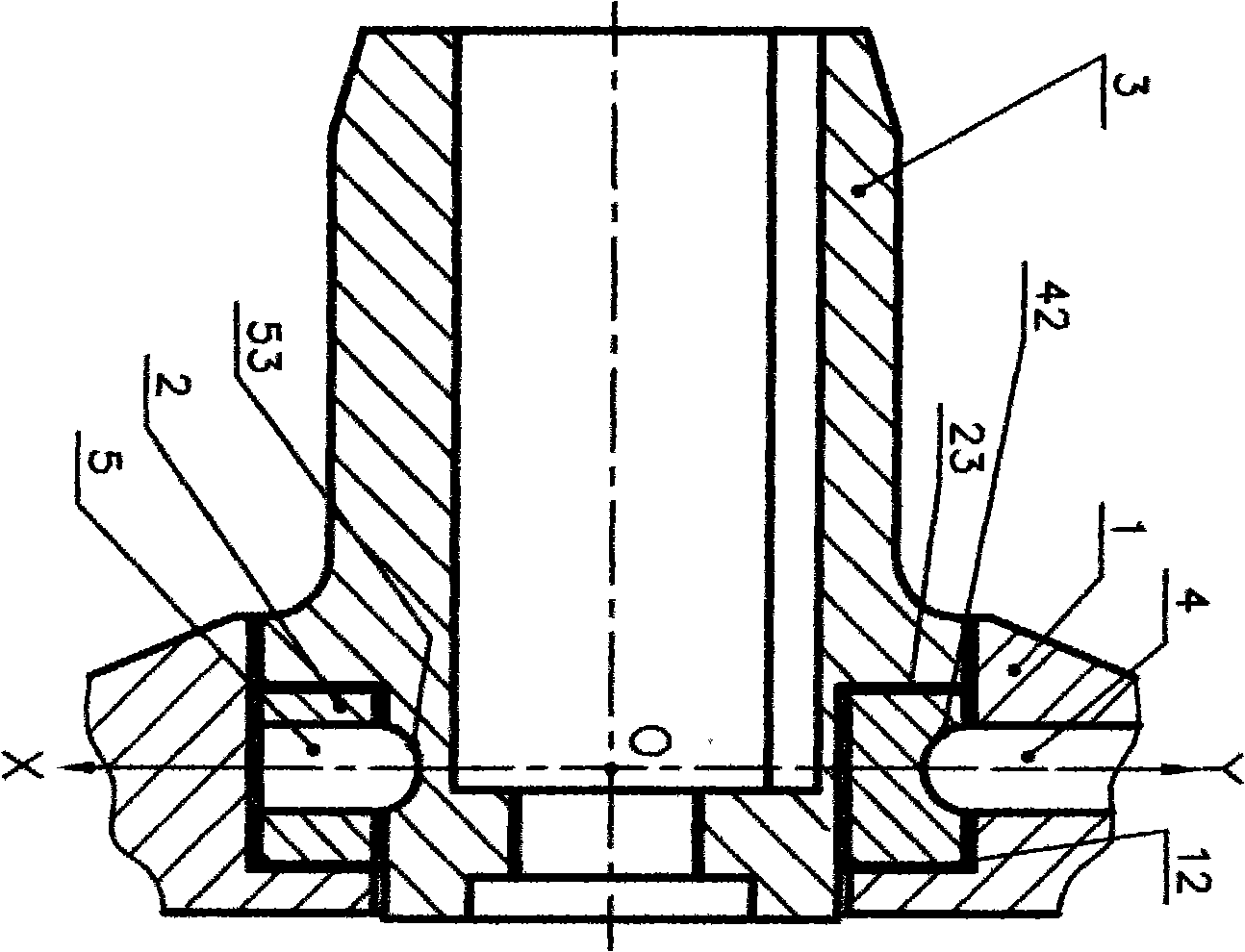
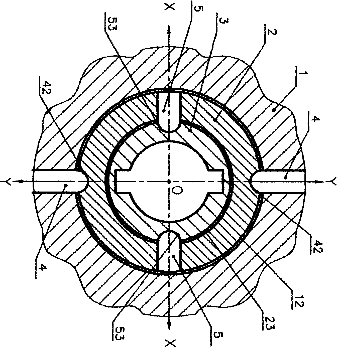
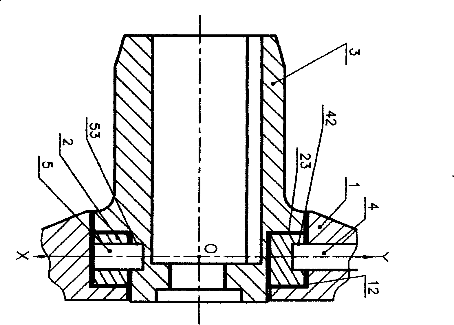
[0023] refer to Figure 1 to Figure 5 .

[0024] The present invention provides an automatic adjustment granulation mechanism that achieves approximately the same contact pressure between the cutters 8 and the template 7 during granulation.

[0025] The object of the present invention is accomplished in the following manner:

[0026] An automatic adjustment granulation mechanism, including a knife holder 1, a swing ring 2, and a shaft sleeve 3; the knife holder 1 and the swing ring 2 are connected through two external torque transmission rods 4, and the swing ring 2 and the shaft sleeve 3 The torque transmission rod 5 is connected; there is a side gap 12 between the tool holder 1 and the swing ring 2, and a side gap 23 between the swing ring 2 and the bushing 3; multiple cutting knives 8 are installed on the knife holder 1; two external torque transmission rods 4. The outer end is fixedly connected to the tool rest 1; the outer ends of the two inner torque transmission rods ...


PUM


Abstract

The invention provides an automatic adjusting granulating mechanism, comprising a tool holder, a swing ring, a shaft sleeve, an external torque transmission rod and an internal torque transmission rod; tool holder is provided with a plurality of cutters; both the connections between the external torque transmission rod and the swing rod, and between the internal torque transmission rod and the shaft sleeve are rotation friction pairs. The rotation friction pair functions to lead the tool holder to swing. The contact pressure of all cutters and a template can be almost consistent by exerting small pushing force on the shaft sleeve. The automatic adjusting granulating mechanism has the advantages that the cutter has little abrasion and long service life during granulating operation; the cutter generates no breaking and has low accident shutdown frequency; the cut grains have no tailings, with good product quality; the operation is reliable and the maintenance is easy.

Description

1 Technical field: [0001] The invention relates to a pelletizing mechanism for underwater pelletizing of hot melt. 2 background technology: [0002] During the hot melt underwater pelletizing process, the hot melt extruded from the template hole is pelletized by using multiple cutting knives on the pelletizing mechanism. During the pelletizing operation, the ideal state is that the contact pressure between the cutting edge of each cutter and the template should be roughly the same. Otherwise, the cutting edge with high contact pressure will cause greater wear and even break off. However, due to installation errors and other reasons that are difficult to overcome, it is difficult to achieve this goal for the rigid pelletizing mechanism; The contact pressure between the cutting edge and the template is different. At the same time, when the contact pressure between the cutting edge of individual cutters and the template is too low, the cut particles will be tailed and the pr...

Claims


Application Information

Patent Timeline
IPC IPC(8): B29B9/06
Inventor 陈友清刘兴成陈喆
Owner 辽阳亿方造粒设备有限公司
Learn More