Automatic feeding mechanism

An automatic feeding and feeding technology, which is applied to conveyor objects, conveyor control devices, transportation and packaging, etc., can solve the problems of too many manpower and only one machine can be managed.

Inactive Publication Date: 2008-11-05
姜文国
View PDF0 Cites 2 Cited by
  • Summary
  • Abstract
  • Description
  • Claims
  • Application Information

AI Technical Summary

Problems solved by technology

If the method of manual supplementary feeding is adopted, a worker can usually only manage a limited number of machi

Method used


Image

  • Automatic feeding mechanism
  • Automatic feeding mechanism
  • Automatic feeding mechanism

Examples


Embodiment Construction

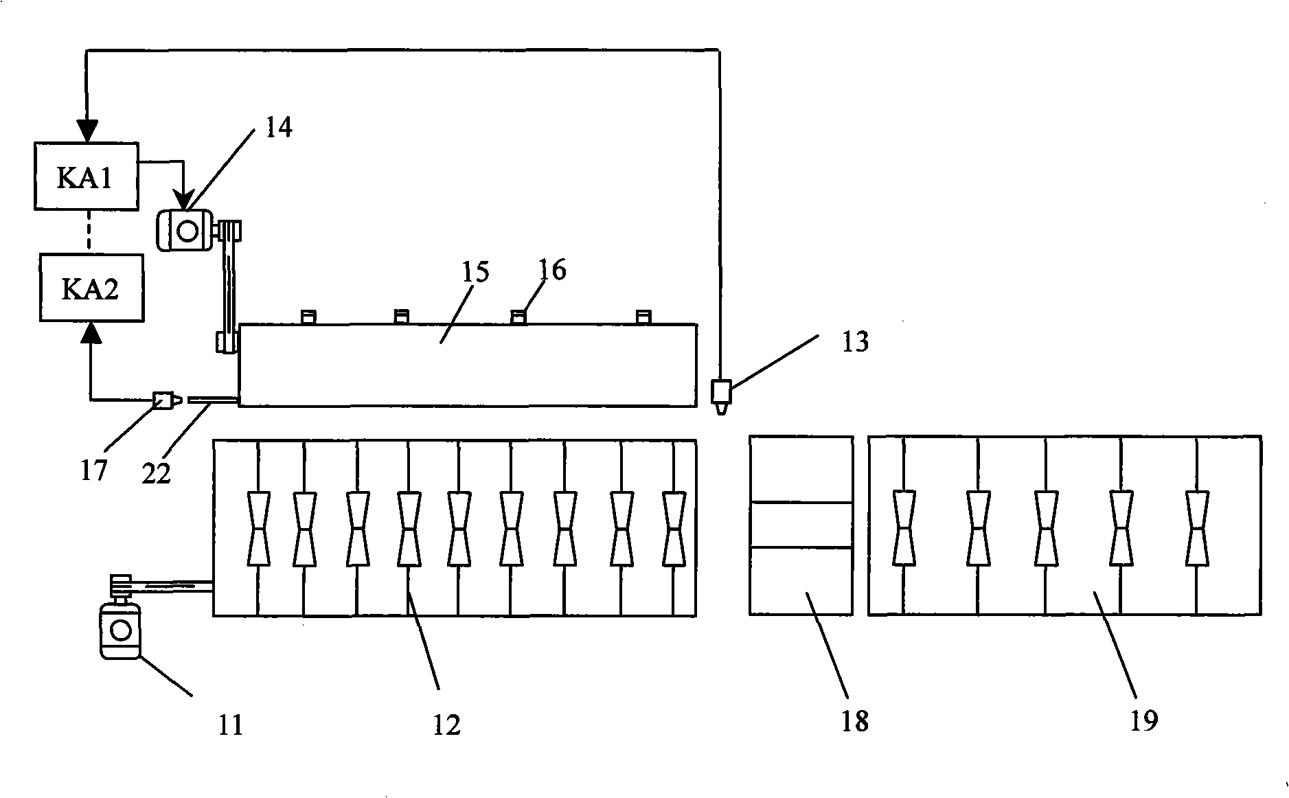
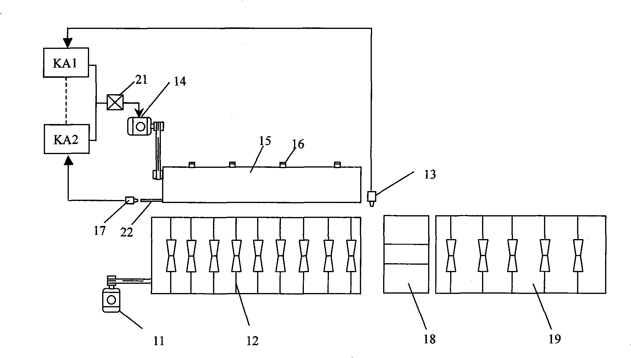
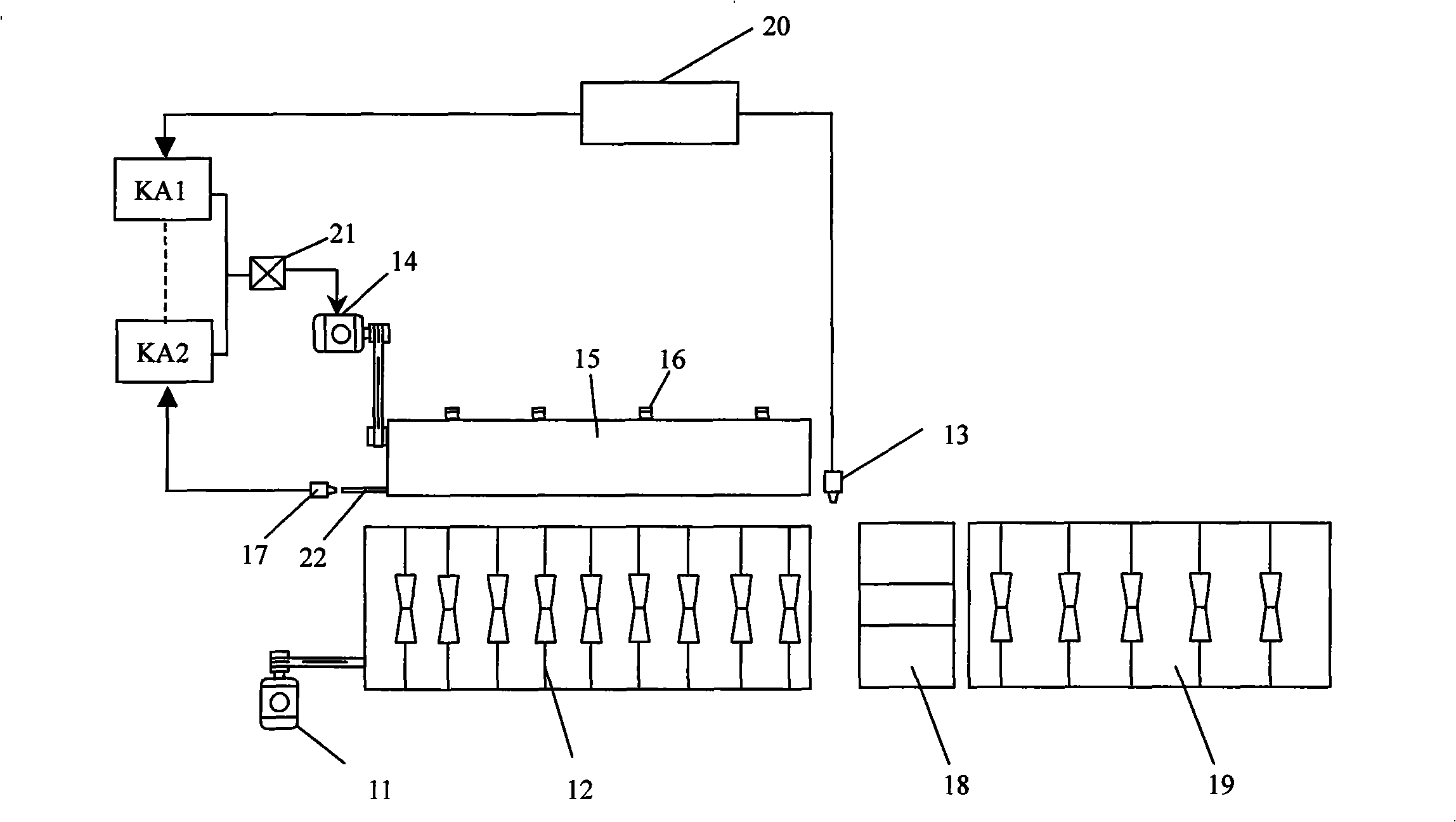
[0011] from figure 1 It can be seen that when the roller group 12 is driven by the driving device 11 composed of a motor and a deceleration mechanism, the feeding roller group 12 rotates in the same direction, so that the workpiece can be fed in the direction that it should move. The feed detection sensor 13 fixedly arranged at the end of the feed roller group 12 adopts a photoelectric switch, such as a normally closed photoelectric switch E3F-DS10Y2. The sensor 13 is facing the workpiece forwarded to the processing area or the processing area 18 by the feed roller set, and when the workpiece is being forwarded into the processing area or the processing area 18, the sensor 13 can sense the presence of the workpiece. At this time, the transistor in the photoelectric switch of the sensor 13 is turned off, and no signal is sent. When the workpiece completely passes through the roller set 12 and then completely enters the machining area 18 through the detection area of ​​the sens...


PUM

PropertyMeasurementUnit
Diameteraaaaaaaaaa

Abstract

The invention provides an automatic charging device, which includes a feeding roller train, a driving device for the feeding roller train, a charging roller that transports the workpiece to the feeding roller train, a driving device for the charging roller, a feed detection sensor at the end of the feeding roller train, a charging roller detector and a relay that is connected with the charging detection sensor to control the On/Off of the driving device of the charring roller. Meanwhile, the charging detection sensor signal can also be connected with a delay circuit to meet the demands of different feeding speeds. With the automatic charging device provided by the invention, the charging of long rods can be made automatically; one worker can manage a plurality of machines, which can considerably improve the working efficiency.

Description

technical field [0001] The invention relates to a feeding mechanism, in particular to an automatic feeding mechanism for a long metal rod. Background technique [0002] Metal parts, such as metal rods, need to be automatically fed forward during processing. Usually, a roller group is used to roll forward. The metal rod is placed on the roller group, and the roller group is driven to feed forward. Once in the machining or processing area, new workpieces need to be placed. If the manual supplementary feeding method is adopted, a worker can usually only manage a limited number of machines, and if the machine processing speed is fast, even a worker can only manage one machine. This requires more manpower. SUMMARY OF THE INVENTION [0003] The purpose of the present invention is to provide a new type of automatic feeding mechanism, which can continuously and automatically feed materials. Coupled with an appropriate automatic unloading mechanism, there is almost no need for m...

Claims


Application Information

Patent Timeline
IPC IPC(8): B65G43/08B65G13/00B65G47/04
Inventor 姜文国
Owner 姜文国
Why Eureka
Try Eureka