Laser radar transmission type coaxial transmitting and receiving equipment

A laser radar and receiving device technology, applied in the field of laser radar transmitting and receiving devices, can solve the problems of non-parallel transmitting optical axis and receiving optical axis, correction error of radar overlap area, high processing and installation cost, and easy installation and debugging. , The effect of stable and reliable work and low cost

Active Publication Date: 2008-11-05
ANHUI INST OF OPTICS & FINE MECHANICS - CHINESE ACAD OF SCI
View PDF0 Cites 23 Cited by
  • Summary
  • Abstract
  • Description
  • Claims
  • Application Information

AI Technical Summary

Benefits of technology

This patented technology describes various technical improvements over existing technologies like LC'S or CWL systems. These new techniques aim to improve upon these traditional methods while maintain their benefits. They include improved efficiency, reduced size, simplified construction process, elimination of multiple sources of noise, increased sensitivity, higher precision measurements, longer life span without requiring repairs, lower costs compared to current alternatives, and more precise alignment than previous ones. Additionally, they provide means to detect reflected lights caused by ambient air particles instead of relying solely on the presence of any materials themselves. Overall, these innovations enhances the performance and functionality of the overall equipment.

Problems solved by technology

Technological Problem addressed in this patents relates to improving the accuracy and reliability of measuring atmospheratic environmental parameters like altitude, wind speed, humidity levels, particle size distributions, turbulence intensity, etc., without compromising their integrity due to variations caused by factors other than constant pressure. Existing methods involve multiple components which require precise alignment during installation, resulting in instabilities when subjected to vibration forces. Additionally, current solutions either lack sufficient precision or rely heavily relying upon temperatures controlled within specific ranges, causing unstable measurements over time.

Method used


Image

  • Laser radar transmission type coaxial transmitting and receiving equipment

Examples


Embodiment Construction

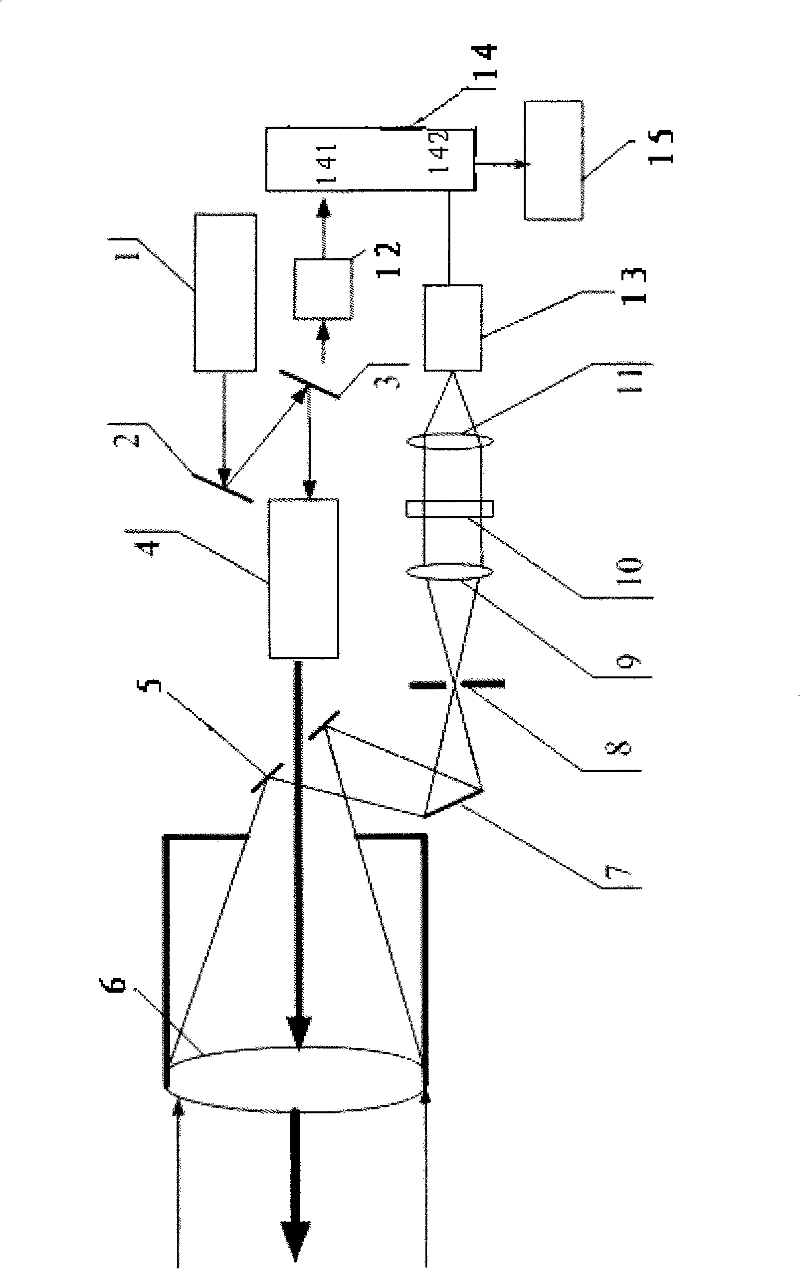
[0011] see figure 1 , laser 1, reflector (2, 3), concave lens 4, reflector 5 and aspheric mirror 6 whose center is a through hole are placed in sequence on the emission optical path; wherein, reflector (2, 3) is two equal to The optical path is at an angle of 45 degrees and is arranged parallel to each other as a plane reflector. The reflector 5 is a plane reflector, and the angle between it and the emission light path is 45 degrees. The diameter of the aspheric mirror 6 is 160mm and the focal length is 500mm. It is coated with an anti-reflection dielectric film with a central wavelength of 532nm, a bandwidth of 50nm, and a transmittance of 99%. The matching relationship between the concave lens 4 and the aspheric mirror 6 is that the divergence angle is 50μrad. An aspheric mirror 6 and a reflector 5 are sequentially arranged on the receiving optical path, and a reflective mirror 7, an aperture 8, a focusing lens 9, an optical filter 10, a focusing lens 11 and a photodetector ...


PUM

PropertyMeasurementUnit
Center wavelengthaaaaaaaaaa
Bandwidthaaaaaaaaaa
Diameteraaaaaaaaaa

Abstract

The present invention discloses a laser radar transmission-type coaxial transmitting and receiving device. (a) The transmission light path is provided with a laser (1), a concave lens (4), a reflecting mirror (5) which is provided with an angle of 40-50 DEG to the light path, and an aspherical mirror (6) which are provided in sequence. (b) A phototube (12) which has an output end electrically connected with the synchronous triggering input port (141) of the photon counter (14) is provided at the position near the concave lens (4). (c) The receiving light path is provided with the aspherical mirror (6) and the reflecting mirror (5) in sequence. The reflecting light path of the reflecting mirror (5) is provided with a reflecting mirror (7), a diaphragm (8), a focusing lens (9), a color filter (10), a focusing lens (1) and a photoelectric detector (13) which are connected in sequence. The output end of the photoelectric detector (13) is electrically connected with the input port (142) of the photon counter (14). The device of the invention has the advantages of simple structure, easy installation and debugging, low cost, stable and reliable work and convenient maintenance. The device can be widely applied in the laser radar.

Description


Claims


Application Information

Patent Timeline
Owner ANHUI INST OF OPTICS & FINE MECHANICS - CHINESE ACAD OF SCI
Why Eureka
Try Eureka