Method and apparatus for cleanness continuously supplying paint to varnished wire painting groove

An enameled wire and paint supply technology, which is applied in the field of enameled wire painting, can solve problems such as uneven viscosity distribution, hidden dangers of breakdown voltage performance, and poor surface quality of enameled wire, so as to achieve uniform viscosity distribution of the original paint, improve process control ability, reduce The effect of contact area

Inactive Publication Date: 2008-11-05
NANXIANG GROUP
View PDF0 Cites 5 Cited by
  • Summary
  • Abstract
  • Description
  • Claims
  • Application Information

AI Technical Summary

Problems solved by technology

[0004] 1. With the continuation of production time, the viscosity of the original paint in the paint tank is getting higher and higher, and the viscosity distribution in the whole paint tank is uneven, making it difficult to control the thickness of the paint film;
[0005] 2. The original paint has a large contact area with the air. The solid particles floating in the air, the original paint does not flow, and the accumulated dirt is not self-cleaning. It is easy to adhere to the wire and form paint bumps, leaving hidden dangers for the breakdown voltage resistance;
[0006] 3. The surface quality of the enameled wire is very poor, and the surface friction coefficient is very large, generally greater than 0.10, which reduces the suitability of the enameled wire during use

Method used


Image

  • Method and apparatus for cleanness continuously supplying paint to varnished wire painting groove
  • Method and apparatus for cleanness continuously supplying paint to varnished wire painting groove

Examples


Embodiment Construction

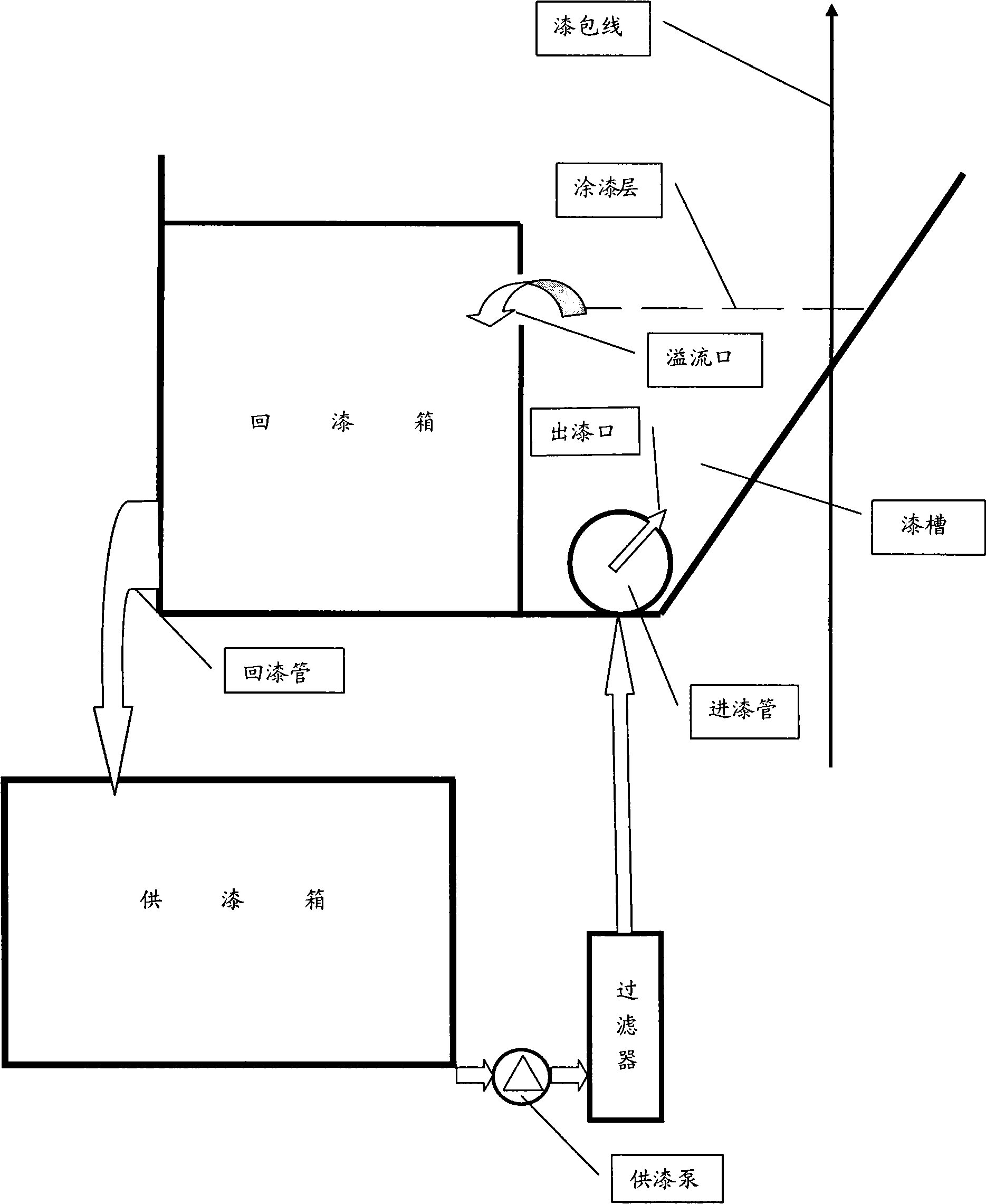
[0018] exist figure 2 Among them, the cleaning and continuous paint supply device of the enameled wire paint tank of the present invention is that a paint inlet pipe is arranged at the bottom of the paint tank along the length direction of the paint tank, and several paint outlets are distributed axially on the paint inlet tube. Configure the paint return chamber, set the overflow port above the partition between the paint return chamber and the paint tank, the overflow port is set along the length of the paint return chamber, the bottom of the paint return chamber is connected to the paint supply box through the paint return pipe, and the paint supply box is connected to the paint supply The pump and the paint supply pump are connected to the filter through two sets of pipelines, and the filter is connected to the paint pipe through the pipeline.

[0019] When the enameled wire is continuously painted in the paint tank, the clean and continuous paint supply method is to set ...


PUM


Abstract

The invention provides a continuous cleaning paint supply method of the enameled wire paint groove, wherein a paint supply case is provided. The original paint is continuously pressed into a filter through a paint supply pump. Two sets of pipe filters are provided at the outside of the paint supply pump. The compound filtering is performed through using a melting spray filter core, so that the original paint is transmitted to paint intake pipes after being filtered. The original paint flows into a paint groove evenly from a paint outlet arranged axially of the paint intake pipes. A paint return chamber is arranged on one side of the paint groove. An overflow port is arranged above a baffle plate arranged between the paint return chamber and the paint groove. When the height of the paint is higher than the overflow port, the original paint flows into the paint return chamber from the overflow port and then returns to the paint supply case through the paint return pipe, which completes a primary circulation. Since the paint intake pipes are arranged along the length direction at the bottom of the paint groove, the original paint flows into the paint return chamber along the length direction of the paint return chamber. Thus, the viscosity of the original paint in the paint groove keeps in line. The paint return chamber is made of steel plate, connected with the paint supply case through the paint return chamber, without exposing the return paint in the air, thereby reducing the evaporation of the original paint for more than1 / 2. When reflowing, the original paint on the coating layer turns over the overflow port, and carries the paint with impurity into the paint return chamber, enters the paint intake pipe again through the paint supply pump and the filter from the paint supply case, which ensures the cleaness of the original paint and increase the quality of the paint surface.

Description

technical field [0001] The invention belongs to the technical field of enameled wire painting, and in particular relates to a method and device for cleaning and continuously supplying paint to enameled wire painting tanks. Background technique [0002] The enameled wire painting process is also called felt painting. It has a simple structure and is easy to operate. There are still many equipments using this method. When painting, the bare wire passes through the paint tank, and is coated with insulating varnish or original paint, and the felt above the paint tank wipes off the excess original paint. The consumed original paint is replenished by the raised paint tank through the paint pipeline and valve. The paint tank only has the original paint replenished, and there is no return path. This is because the position of the paint tank is higher than the paint tank and cannot be returned. This method For the process equipment, see figure 1 . [0003] The disadvantages of thi...

Claims


Application Information

Patent Timeline
Patent Type & Authority Applications(China)
IPC IPC(8): H01B13/16
Inventor 徐继良
Owner NANXIANG GROUP
Why Eureka
Try Eureka