Equipment for rotating permanent magnetism

A technology of magnetic equipment and permanent magnet, applied in the field of medical treatment and rehabilitation, can solve the problems of uncontrollable, unclear target area and high cost, and achieve the effect of high safety and stability, accurate treatment effect and breakthrough of bottleneck.

Inactive Publication Date: 2008-11-12
胡振华
View PDF1 Cites 2 Cited by
  • Summary
  • Abstract
  • Description
  • Claims
  • Application Information

AI Technical Summary

Problems solved by technology

The condition of the equipment at work and the spatial distribution of the magnetic force lines generated by it are as follows: figure 1 It can be seen from the figure that the irradiated patient is exposed to the magnetic field in a large area, and the angles at which the magnetic field lines enter the various parts of the human body and the field strengths of the irradiated parts of the patient are different. Obviously, the existing This kind of permanent magnet gyromagnetic device has the following problems: 1) the target area is not clear during the use of the device, the field strength of each point of the patient's irradiated part is not equal and uncontrollable, and the directions of the field vectors of each point of the patient's irradiated part are different, so , although in clinical use, it is effective for some indications, but it is only some macroscopic results, and it does not indicate where, how strong, and what form of magnetic field acts on the patient. As this kind of equipment can no longer be further improved and developed, this situation needs to be improved urgently; 2) the magnetic stack is too large in size, high in cost, and high in cost; Excessive magnetic leakage is generated during use, which brings magnetic pollution to a large area around; 4) Excessively large magnetic stacks rotate at high speed during use, posing safety hazards

Method used


Image

  • Equipment for rotating permanent magnetism
  • Equipment for rotating permanent magnetism
  • Equipment for rotating permanent magnetism

Examples


Embodiment 1

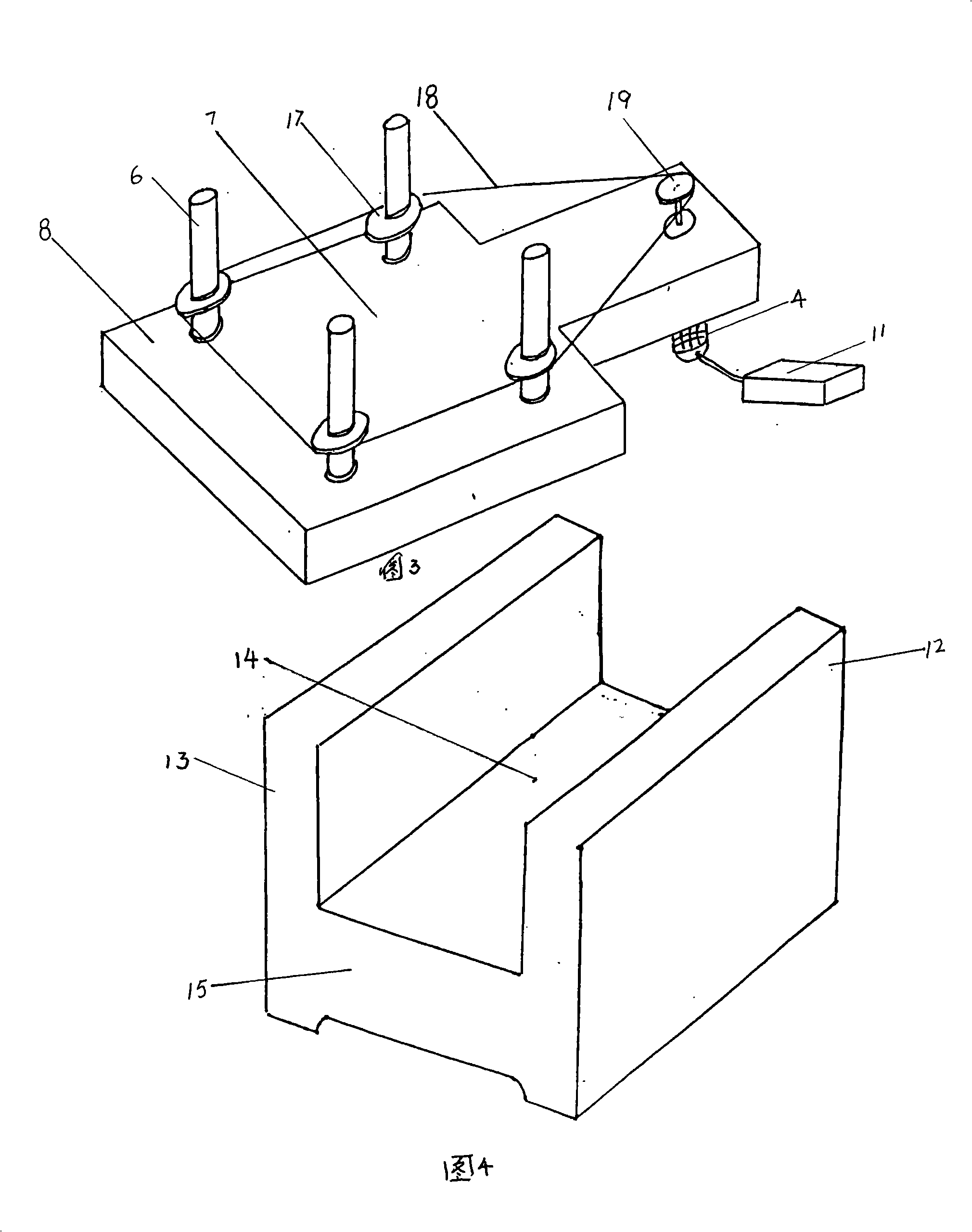
[0045] A permanent magnet gyromagnetic device, as shown in Figure 3, four magnetized permanent magnet rods 6 with the same length and cross-sectional shape are erected on the four corners of a regular quadrilateral or rectangle, two on each side, and two on the corresponding side. The axis distances of the permanent magnet rods 6 are equal;

[0046] Four permanent magnet bars 6 can be placed on the base 8, and the specific connection between the permanent magnet bars 6 and the base 8 can be found in Figure 5 , that is, the permanent magnet rod 6 and the shaft head 20 are fixedly connected into one body, and the shaft head 20 is movably connected with the base 8 through the bearing bush 21;

[0047] See Fig. 3, on the same horizontal plane at the lower ends of the four permanent magnet rods 6, drag wheels 17 made of non-magnetic materials are respectively fixed, the drive motor 4 drives the transmission wheel 19 to rotate, and each drag wheel is dragged by the transmission cha...

Embodiment 2

[0054] A permanent magnet gyromagnetic device, such as Image 6 As shown, four magnetized finite-length permanent magnet rods 6 stand on the four corners of a regular quadrilateral or a rectangle, and the distances from the centerlines of the permanent magnet rods on both sides are equal, and the sick bed 9 can be placed on the permanent magnet rods 6 between;

[0055] Such as Figure 7 , 11 As shown, the four permanent magnet rods 6 can be installed in four housings 22 that match the permanent magnet rods 6 respectively. The lower end of the housing 22 forms a shaft head 20, and the shaft head 20 passes through the base 8 and moves with the base 8 through the bearing bush 21. connection; on the same horizontal plane as the lower end of the shaft head 20, gears 10 made of non-magnetic materials are respectively fixed;

[0056] Such as Figure 7 , 8 11, there is a large gear 16 in the middle of the four shaft heads 20, the large gear 16 meshes with four small gears 10, the...

Embodiment 3

[0059] A permanent magnet gyromagnetic device, such as Image 6 As shown, four magnetized finite-length permanent magnet rods 6 stand on the four corners of a regular quadrilateral or a rectangle, and the distances from the centerlines of the permanent magnet rods on both sides are equal, and the sick bed 9 can be placed on the permanent magnet rods 6 between;

[0060] Such as Figure 9 , 10 , 12, the four permanent magnet bars 6 can be respectively installed in four housings 22 that match the permanent magnet bars 6, the lower end of the housing 22 forms a shaft head 20, and the shaft head 20 passes through the base 8 through the bearing bush 21 and the base 8. Movably connected; the lower ends of the four axle heads 20 are on the same horizontal plane, respectively fixed with a transmission wheel 19 and three drag wheels 17 made of non-magnetic materials, and the transmission chain 18 and the transmission wheel 19 and three drag wheels 17 matches;

[0061] The driving mo...


PUM

PropertyMeasurementUnit
heightaaaaaaaaaa
diameteraaaaaaaaaa

Abstract

The invention discloses a permanent magnet gyromagnetic apparatus, which is used in the time-varying magnetic field field and particularly suitable for the medical treatment and rehabilitation field. The permanent magnet gyromagnetic apparatus comprises four permanent bar magnets which are respectively arranged on four corners of a quadrangle, wherein, a target area is formed in the quadrangular area. The permanent magnet gyromagnetic apparatus has the advantages of definite target area, measurable single magnetic field, small magnet volume, safe operation, selectable field density and knowable field form, and fundamentally solves the problem that the prior apparatus can not be further improved and developed and overcomes the technical difficulty with bottleneck property in the magnetic medical treatment field.

Description

[0001] Field [0002] The invention discloses a permanent magnet gyromagnetic device, that is, a variable magnetic field generator using permanent magnet materials as a magnetic source, which is used in the field of magnetic fields that need to change with time, and is especially suitable for the fields of medical treatment and rehabilitation. The magnetic field it generates can be used in occasions that require a time-varying magnetic field environment and special mechanical behavior, especially the magnetic field it generates is used to irradiate specific parts of the human body to achieve the purpose of treatment or rehabilitation, and is especially suitable for Treatment of human pain, relief of muscle fatigue, improvement of microcirculation system, etc. Background of the invention [0003] There are two ways to generate a magnetic field. One is to use a energized coil, and the other is to use a permanent magnet as a magnetic source. The former has the disadvantages of he...

Claims


Application Information

Patent Timeline
Patent Type & Authority Applications(China)
IPC IPC(8): A61N2/06A61N2/12H01F7/02H01F41/02
Inventor 胡振华
Owner 胡振华
Why Eureka
Try Eureka