Power type ship propelling system

A technology for propulsion systems and ships, which is applied in ship propulsion, propulsion components, ships, etc., can solve the problems of large resistance of ships 1 and easy injuries and damages caused by people in the sea

Inactive Publication Date: 2008-11-12
SOLAS SCI & ENG
View PDF0 Cites 4 Cited by
  • Summary
  • Abstract
  • Description
  • Claims
  • Application Information

AI Technical Summary

Problems solved by technology

[0003] Because the components of the above-mentioned boat 1, such as the A-frame 14, the rudder 17 and the propeller 15, are all located below the bottom 13, it is easy to cause the boat 1 to suffer too much resistance when propelled, and these exposed components are also exposed. Easy to touch the reef or planktonic plank and cause damage
In addition, the engine 11 of the boat 1 is usually located in the center of the boat 1, which limits the use of space inside the boat 1.
[0004] As shown in Figure 2, the known large boat 2, although the usable space inside the boat 2 is much smaller than that of the small boat 1, the engine 21 of the boat 2 is still in the center of the boat 2, which still affects the 2 The utilization rate of the internal space. Moreover, the propeller and the rudder are still located under the boat. In addition to being easy to collide with hidden reefs, it is easy to cause damage to people in the sea or marine conservation organisms such as manatees, and may even be caught by the propeller 22 because of seaweed The root of the propeller 22 was broken, causing damage to the plants in the sea
In addition, when the boat 2 is retreating, it is necessary to control the steering of the boat 2 through a thruster 24 (Bow thrusters) located at the bow 23 and a thruster 26 (Stern thrusters) located at the stern 25, but the two propulsion The components of the device 24, 26 also take up a lot of space inside the boat 2

Method used


Image

  • Power type ship propelling system
  • Power type ship propelling system
  • Power type ship propelling system

Examples


Embodiment Construction

[0036] The following preferred embodiments are listed in conjunction with the accompanying drawings to describe the structure and effects of the present invention in detail.

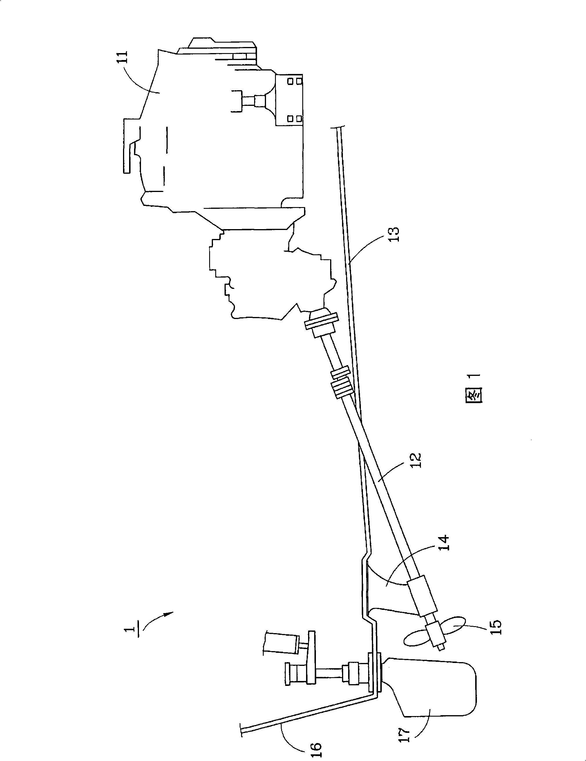
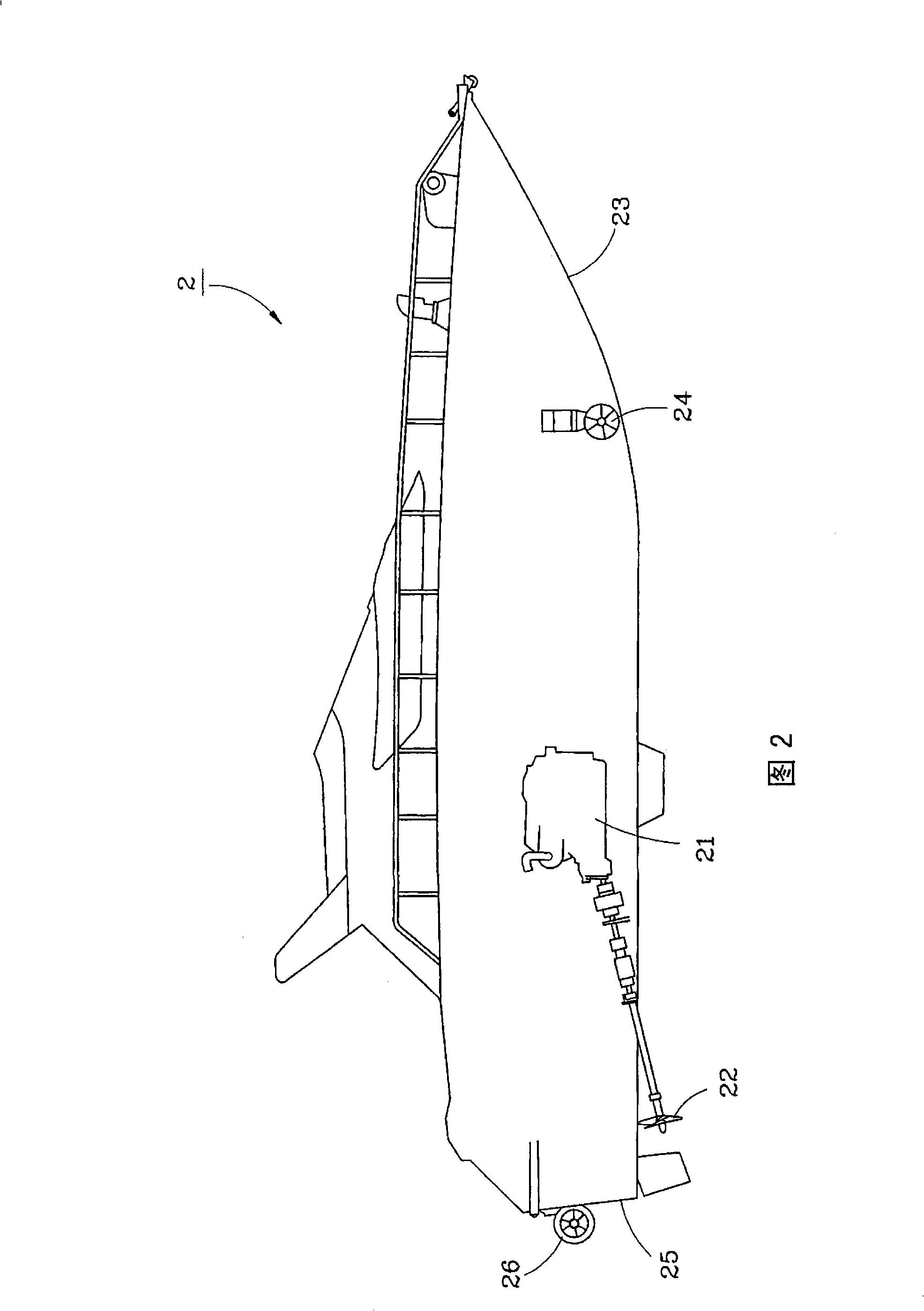
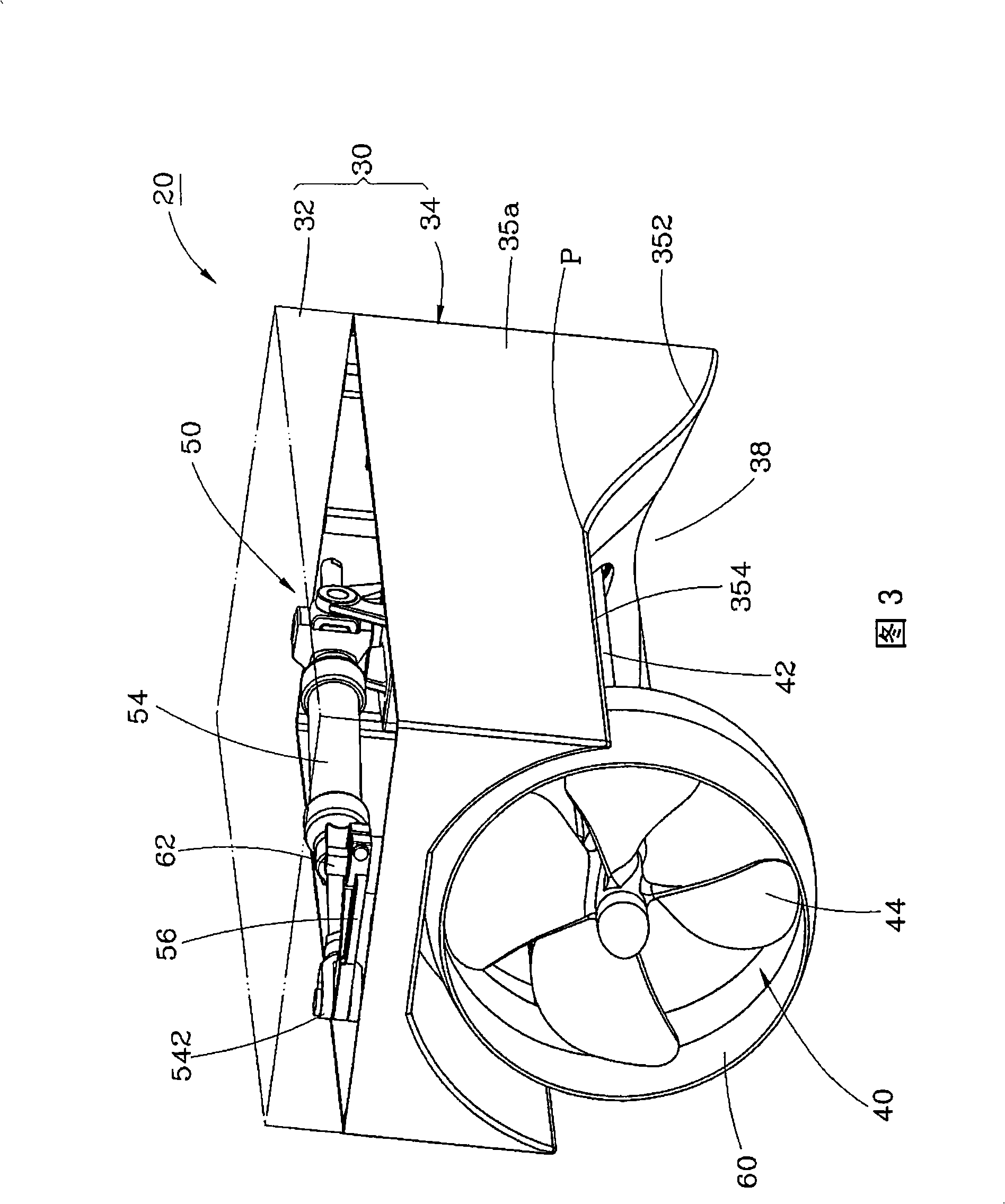
[0037] Please refer to Fig. 3 and Fig. 4 first, the propulsion system 20 of a preferred embodiment of the present invention is installed in a small power boat, the power boat includes a hull 10, and an engine 12 is installed inside the hull 10, The engine 12 is located near the stern 14 of the hull 10 , and the stern 14 of the hull 10 is provided with a stern deck 16 . The propulsion system 20 includes a casing 30 , a propeller 40 , a hydraulic drive device 50 and a spoiler 60 .

[0038] The front end of the casing 30 is fixed on the stern 14 of the power boat and is located below the stern deck 16 , as shown in FIG. 8 . The casing 30 has a cover 32 and a base 34 , the cover 32 covers the top edge of the base 34 , so that a chamber 36 is formed between the cover 32 and the base 34 . The base 34 has two...


PUM


Abstract

The invention relates to a propulsion system of a power-style ship, comprising a casing, a propeller, an oil-pressure driving device and an air guide sleeve. The casing is connected with a stern part of the power-styled ship and is provided with a chamber and a guiding channel. The propeller is arranged on the stern part and is positioned in the guiding channel. The oil-pressure driving device is arranged in the chamber of the casing and is provided with a driving part and a linkage part pivoted with the driving part. The air guide sleeve covers the propeller with the common axis and is pivoted with the linkage part to lead the linkage part to be driven by the driving part so as to drive the air guide sleeve adopting the center of the propeller as an axes to partially sway to the left and right, not only controlling the left or right turning of the power-style ship but also controlling the left or right backing of the ship when the propeller reverses and leading the engine of the power-style ship to be arranged at a position near the stern part so as to enlarge the internal space.

Description

technical field [0001] The present invention relates to a power boat, in particular to a propulsion system for a power boat, which can effectively expand the space inside the power boat. Background technique [0002] Please first refer to the known small boat 1 shown in Fig. 1, the engine 11 inside the boat 1 is connected to a drive shaft 12, and the drive shaft 12 passes through the bottom 13 of the boat 1 obliquely downwards, and passes through an A frame 14 sets Suppose and connect a propeller 15. The boat 1 is provided with a rudder 17 at the stern 16 . [0003] Because the components of the above-mentioned boat 1, such as the A-frame 14, the rudder 17 and the propeller 15, are all located below the bottom 13, it is easy to cause the boat 1 to suffer too much resistance when propelled, and these exposed components are also exposed. It is easy to touch the reef or planktonic plank and cause damage. In addition, the engine 11 of the boat 1 is usually located in the cent...

Claims


Application Information

Patent Timeline
Patent Type & Authority Applications(China)
IPC IPC(8): B63H5/14
CPCB63H5/16B63H5/14B63H25/48B63H2025/066B63H5/08
Inventor 林允进
Owner SOLAS SCI & ENG
Why Eureka
Try Eureka