
Filler rod sewing machine

A sewing machine and molding technology, which is applied to sewing machine components, sewing machine control devices, sewing equipment, etc., can solve problems such as hindering operations, and achieve the effect of improving workability and stable posture

Active Publication Date: 2008-11-12
JUKI CORP
View PDF5 Cites 5 Cited by
  • Summary
  • Abstract
  • Description
  • Claims
  • Application Information

AI Technical Summary

Problems solved by technology

In the above-mentioned pressing position, the front end of the holder or the cloth guide (guide member) described in Patent Document 2 is in the position between the two sewing needles. When the operator opens the face of the sewing machine frame for maintenance, hinder homework

Method used


Image

  • Filler rod sewing machine
  • Filler rod sewing machine
  • Filler rod sewing machine

Examples


Embodiment Construction

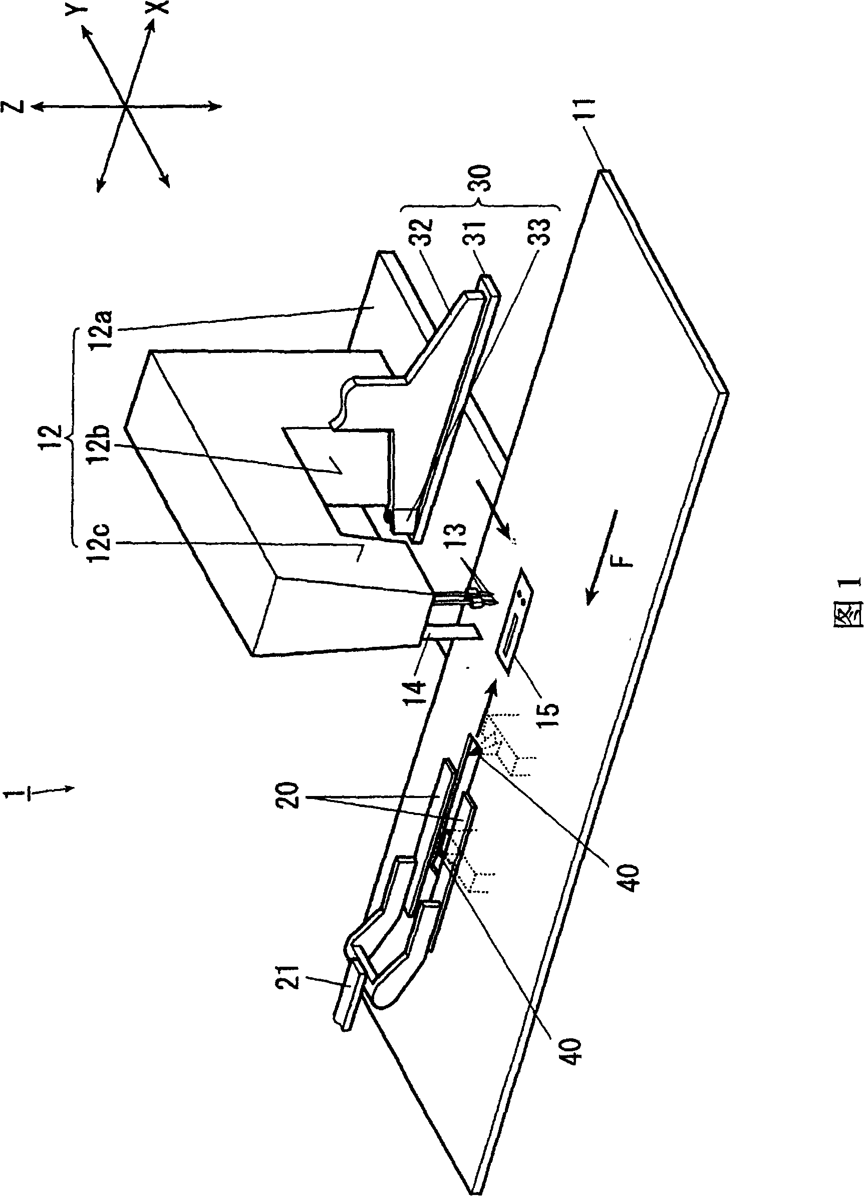
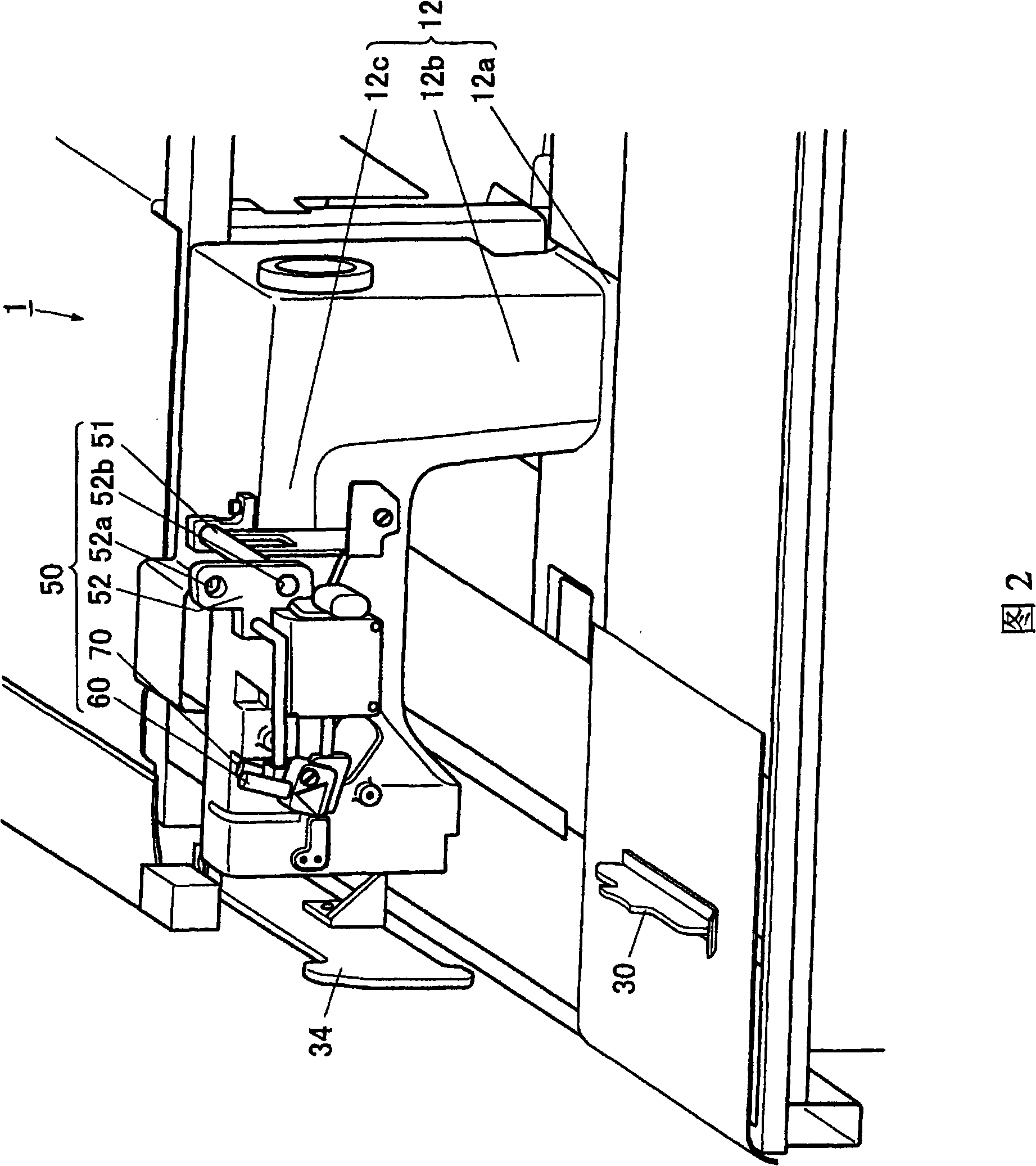
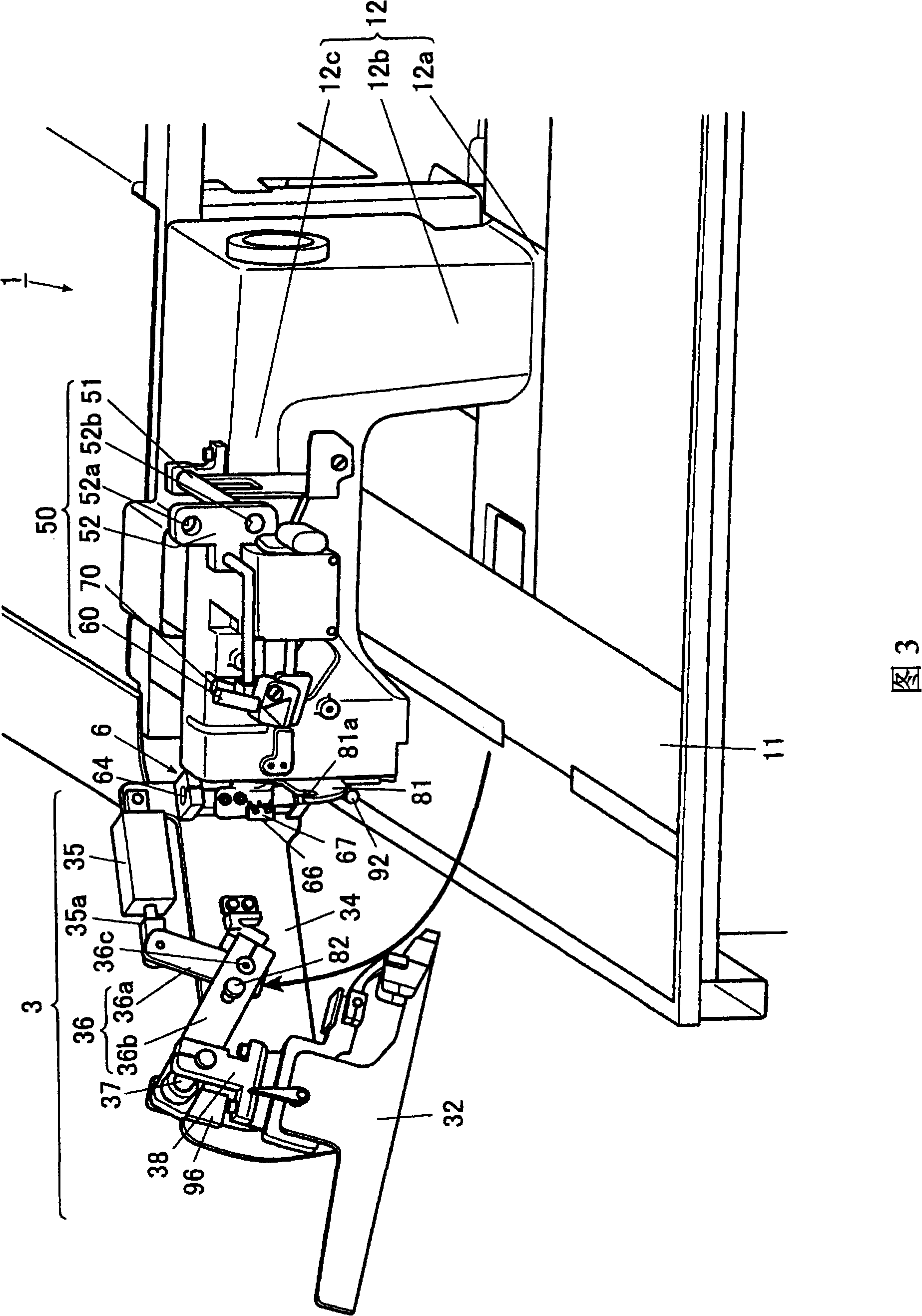
[0039] Next, referring to the accompanying drawings, the best mode for carrying out the present invention will be described in detail by taking a panel sewing sewing machine as an example. In addition, in this embodiment, each direction is determined based on the XYZ axes shown in the figure, the Z-axis direction coincides with the vertical movement direction of the central knife described later, and the plane on which the sewing operation is performed is perpendicular to the Z-axis direction. , the direction parallel to the working plane and feeding the cloth is the X-axis direction, and the direction parallel to the working plane and perpendicular to the X-axis direction is the Y-axis direction.

[0040]

[0041] As shown in FIG. 1 , the panel sewing sewing machine 1 is a sewing machine that uses two sewing needles 13 and 13 that move up and down to form two parallel stitches on the sewn object composed of the main fabric and the panel fabric. The stitches are used to sew ...


PUM


Abstract

The invention relates to a panel strip sewing machine that prevents a sewing needle from broken caused by incorrect action of a maintainer. The panel strip sewing machine has a sewing machine body, a central cutter mechanism, a maintainer mechanism that has a maintainer, a maintainer driving unit and a leading unit. The maintainer has a bottom plate portion, a vertical plate portion and a leadingelement; a maintainer supporting shaft that is supported in upper and lower directions in a manner that supports the maintainer mechanism freely and rotationally; a cloth moving mechanism that has a pair of large presser foots and a motion main cloth and panel cloth conveying mover through the cloth feeding direction of the large presser foots, wherein the maintainer supporting shaft is provided with a rotation preventing unit that is provided in exterior side of the sewing machine body and in downriver side of cloth feeding direction opposite to the sewing machine body to prevent rotation ofthe maintainer body centered by the maintainer supporting shaft before moving to the upriver side of the cloth feeding direction between two sewing needles opposite to front end of the leading element along the leading unit.

Description

technical field [0001] The present invention relates to a panel sewing sewing machine, which sews panel fabric to the main fabric of clothes, and simultaneously forms prescribed slits on the main fabric and the panel fabric. Background technique [0002] Conventionally, in sewing using a molding sewing machine, a main cloth is placed on the upper surface of the needle plate, a molding cloth is stacked on top of it, and a holder having an inverted T-shaped cross section is placed from the top thereof. It consists of a bottom plate and a vertical plate vertically erected on its upper surface. And the holding body holds the main fabric and the molding cloth in a state where both ends of the molding cloth are folded back along the bottom plate portion and the vertical plate portion of the holding body, and is moved in a predetermined direction by a feed mechanism, Sewing is performed with two needles that drop needles on both sides of the vertical plate portion of the holder. ...

Claims


Application Information

Patent Timeline
Patent Type & Authority Applications(China)
IPC IPC(8): D05B35/06D05B29/00D05B37/02D05B69/30
Inventor 高濑秀纪小川达矢沟渊顺也平泽裕
Owner JUKI CORP
Learn More