Unidirectional clutch

A one-way clutch and clutch technology, applied in the field of machinery, can solve the problems of slippage, high manufacturing process requirements, and the inability of the automobile engine to start, and achieves the effect of fewer components, overcoming the slippage defect, and a reasonable structure design.

Inactive Publication Date: 2008-11-12
叶常青 +2
View PDF0 Cites 5 Cited by
  • Summary
  • Abstract
  • Description
  • Claims
  • Application Information

AI Technical Summary

Problems solved by technology

The existing one-way clutch has high requirements on the material and manufacturing process of the roller, sleeve and helical spline shaft. After working for a period of time, due to the wear of the inner cavity raceway and the roller, it is easy to slip, causing the car engine to fail. start

Method used


Image

  • Unidirectional clutch
  • Unidirectional clutch
  • Unidirectional clutch

Examples


Embodiment Construction

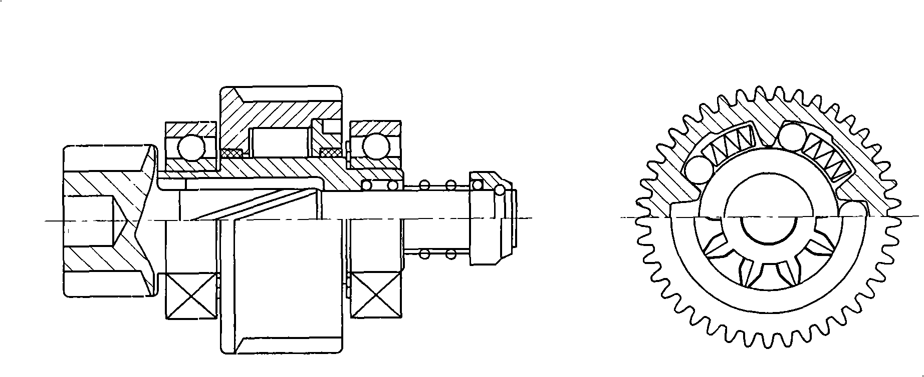
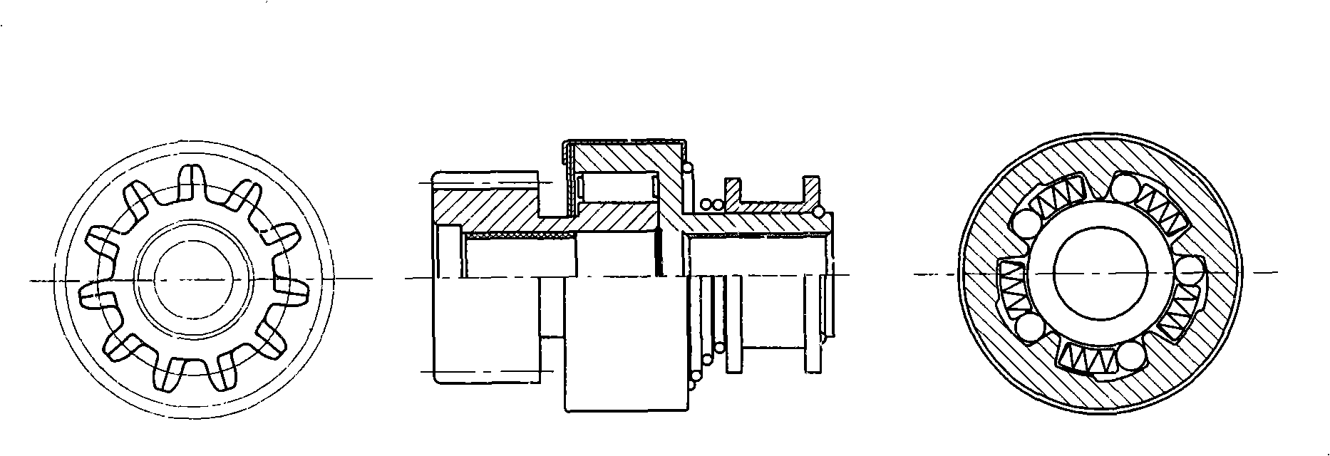
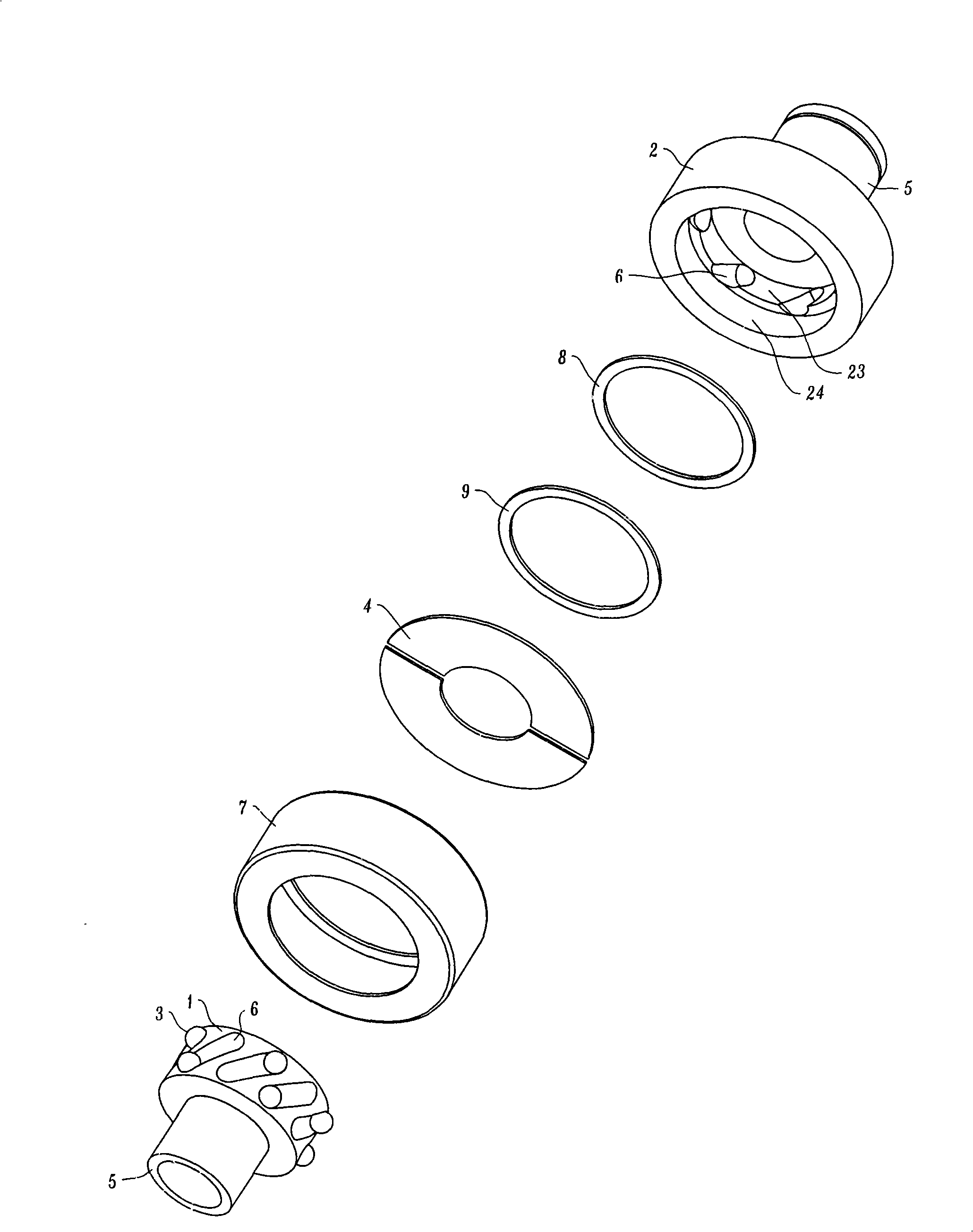
[0025] refer to figure 2 , the rotating body forms a dynamic matching structure on the circumferential surface, the surface of the first rotating body 1 has a semicircular guide groove 6, and the second rotating body 2 is provided with clutch inner and outer cavities 23, 24 with coaxial centerlines, and the clutch inner cavity 23 and The diameter of the first rotating body 1 coincides, and it is sleeved on the first rotating body to form a dynamic fit. Its inner surface has an included angle with the semicircular guide groove 6 on the surface of the first rotating body 1 (projected angle on the surface of the circumferential development. ) in the semicircular guide groove 6, a ball 3 is movably placed in the intersecting cavity of the first rotating body 1 and the second rotating body 2 semicircular guide groove 6, and the clutch outer cavity 24 of the second rotating body 2 forms a ball 3 that can move freely. The cavity, that is, once the ball 3 slides into the clutch outer...


PUM


Abstract

The invention relates to a one-way clutch which comprises a first rotating body and a second rotating body which are dynamically matched with a circle surface. The matching surfaces of the rotating bodies are respectively provided with semicircular guide grooves which are mutually intersected. A roll ball flexibly rotates in an intersected cavity of the two guide grooves and a cavity is formed by an outer clutch cavity of the second rotating body, in which the roll ball can freely move. The one-way clutch of the invention is characterized in that at least one end of the semicircular guide groove on the surface of the first rotating body, which faces the outer clutch cavity of the second rotating body, is a closed structure, and the semicircular guide groove of the first rotating body enters the outer clutch cavity of the second rotating body by the size where one roll ball can be contained. By the action of the two intersected guide grooves, the roll ball slides to the intersected clearance of the two guide grooves according to the changes of relative rotational speed of the two rotating bodies, thus realizing the meshing of the two rotating bodies. After the roll ball slides away from the guide groove into the cavity of the rotating body, the separation between the two rotating bodies is realized. The roll ball can roll and slide in the guide groove and the cavity so as to overcome the defect of skid caused by sliding wear of the one-way clutch due to the extrusion of a roller and the deformation of a flat spring, etc., thereby prolonging the service life.

Description

[0001] This application is a divisional application: [0002] Filing date of the original application: September 23, 2005, application number: 200510019493.4 [0003] Invention name: one-way clutch mechanism Technical field: [0004] The invention belongs to the mechanical field, and in particular relates to a one-way clutch, which is especially suitable for a mechanism used as a one-way clutch for a vehicle starter. Background technique: [0005] One-way clutches are widely used in the field of automobile starters. The starter is a key small part of the automobile engine, and its failure will directly cause the vehicle to fail to start. At present, the one-way device on the automobile starter, or called the transmission mechanism, mainly makes the starter drive gear mesh with the engine flywheel for transmission and separation. Different types of starters have different one-way devices, and the common ones are roller type, friction plate type, spring type and ratchet type...

Claims


Application Information

Patent Timeline
Patent Type & Authority Applications(China)
IPC IPC(8): F16D41/064
Inventor 叶羽纺叶杉叶常青叶芃叶常彬叶羽纬
Owner 叶常青
Why Eureka
Try Eureka