

Automatic water supply device controlled by soil water potential
An automatic water supply device and soil water potential technology, which is applied in the direction of watering device, valve device, valve operation/release device, etc., can solve the problems of low sensitivity, complex structure, high cost, etc., achieve low cost, reduce operating cost, save energy effect
Inactive Publication Date: 2008-11-19
HENAN AGRICULTURAL UNIVERSITY
View PDF0 Cites 10 Cited by
- Summary
- Abstract
- Description
- Claims
- Application Information
AI Technical Summary
Problems solved by technology
In the 1940s, Dr. L.A.Richards of Cornell University in the United States replaced the dripper in the drip irrigation system with a tensiometer and realized passive control irrigation without energy. However, this equipment has complex structure, high cost, and The disadvantage of low sensitivity
Method used
View moreImage
Smart ImageViewing Examples

Examples
Embodiment 1
Embodiment 2
Login to View More PUM
 Abstract
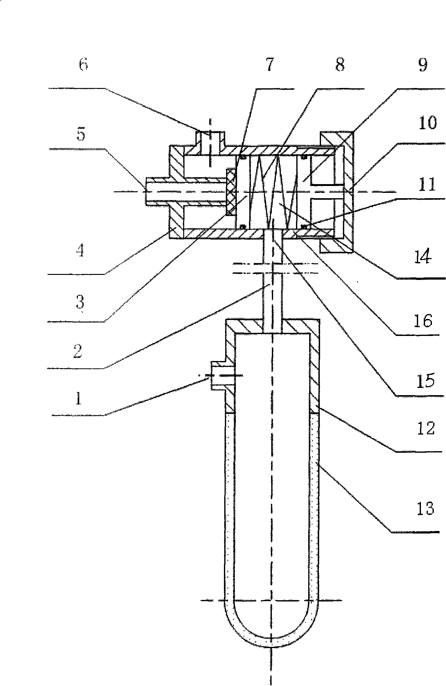
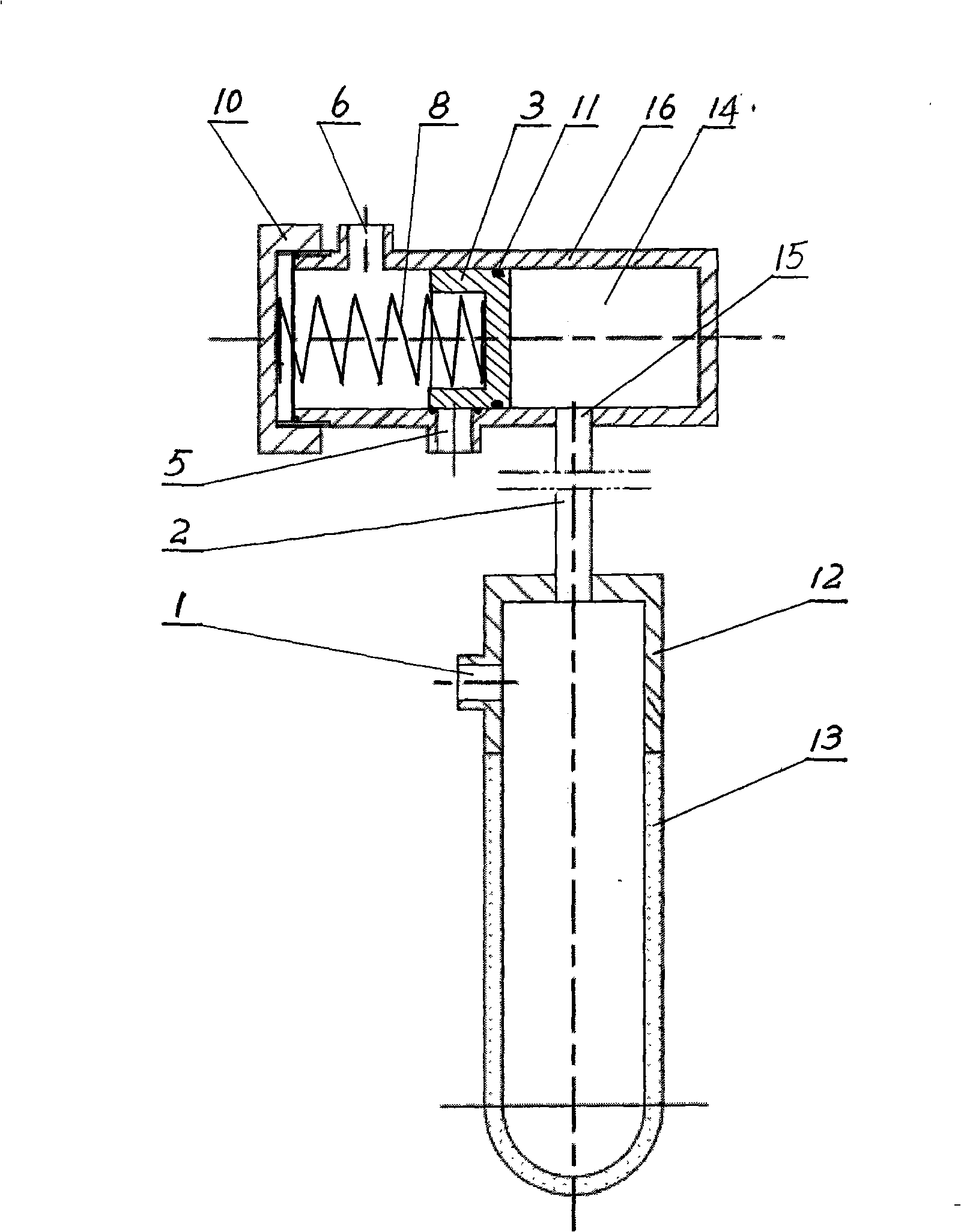
The invention relates to an automatic water supply device for controlling the soil water potential, which comprises a valve and a sensing device communicated with the valve, wherein the sensing device comprises a pottery clay water core, and a cavity for water infusion is arranged inside the sensing device. A spring, a piston and a pressure chamber are arranged in the inner cavity of the valve body; a water inlet opening and a water outlet opening are arranged at the front end of the valve body, wherein the piston is in contact with the water inlet opening, and the sensing hole on the sensing device is communicated with the pressure chamber on the valve through a connecting pipe. In the device, the soil water potential is sensed through the pottery clay water core inserted into the soil, and the movement of the piston is controlled through the negative pressure generated through the soil water potential change to enable the valve to be opened or closed, so that the purpose of automatic water supply can be reached. The device has the advantages of simple structure, low cost, saved energy resource, reduced water resource consumption, greatly reduced operation cost, and wide application prospect in agriculture, stock raising industry and forest industry. Furthermore, the device can perform irrigation in due time according to the water supply demands of the plant crops.
Description
A soil water potential control automatic water supply device technical field The invention relates to a water supply device, mainly a device for automatically controlling water supply by sensing soil water potential. Background technique The existing automatic irrigation system generally adopts the control system of mechanical and electronic hybrid coordination. In the 1940s, Dr. L.A.Richards of Cornell University in the United States replaced the dripper in the drip irrigation system with a tensiometer, realizing passive control irrigation without energy, but this equipment has complex structure, high cost, The disadvantage of low sensitivity. Contents of the invention The object of the present invention is to provide a soil water supply device that can automatically control timely and appropriate water supply, has simple structure, reliable performance, low operating cost and does not require energy. In order to achieve the above object, the technical solution adop...
Claims
Login to View More Application Information
Patent Timeline
 Patent Type & AuthorityApplications(China)
IPC IPC(8): A01G25/16A01G25/00F16K1/00F16K3/24F16K31/122
Inventor汪强何予鹏谭金芳王慧荣
OwnerHENAN AGRICULTURAL UNIVERSITY