Operating pressure adjustable air exhausting brake

A technology of exhaust braking and working pressure, which is applied in the direction of engine components, engine control, machine/engine, etc., can solve the problems of short braking time, braking lag, unstable back pressure value, etc., and achieve sensitive response and control Smooth and reliable effect

Inactive Publication Date: 2008-11-19
李瑞强
View PDF0 Cites 35 Cited by
  • Summary
  • Abstract
  • Description
  • Claims
  • Application Information

AI Technical Summary

Problems solved by technology

[0005] 1. The back pressure is not stable and cannot be adjusted, because the engine speed is not constant, but changes within a certain range, so its back pressure is not a definite value. As the engine speed increases, its back pressure also increases. Increasingly, exceeding the allowable pressure value of the engine will cause harm to the engine itself
Although the maximum back pressure value can be limited by increasing the pressure relief hole, it also cannot solve the problem of unstable back pressure value, and the increase of the pressure relief hole usually reduces the back pressure value (because the design of the pressure relief valve should be based on The maximum speed of the engine is designed, and the speed of the engine is usually lower than its maximum speed), thus reducing the performance of the entire exhaust brake
[0006] 2. Due to the increase of the pressure relief hole, the sensitivity of the exhaust brake is reduced. Because the exhaust brake works by the back pressure of the engine, it takes a certain amount of time to establish the back pressure. After the pressure relief hole is added, the back pressure is established. The pressing time will be longer, which will lead to serious lag of braking, especially when walking on uneven slopes, it may be necessary to brake frequently, and the braking time is very short. Due to the serious lag of braking, it often makes it The braking effect is lost, and in serious cases, it will lead to accidents

Method used


Image

  • Operating pressure adjustable air exhausting brake
  • Operating pressure adjustable air exhausting brake
  • Operating pressure adjustable air exhausting brake

Examples


Embodiment Construction

[0018] The present invention will be further described below in conjunction with the accompanying drawings.

[0019] In order to understand the structural principle of the present invention more clearly, describe the novelty of the present invention, creativity, and compare with other disclosed engine retarder structures, first to figure 1 , figure 2 for analysis.

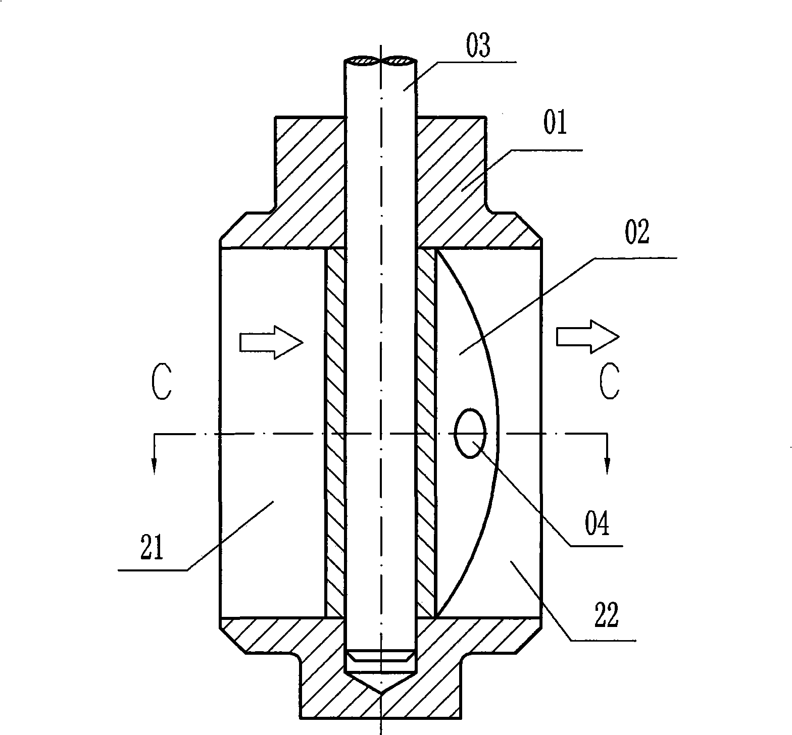
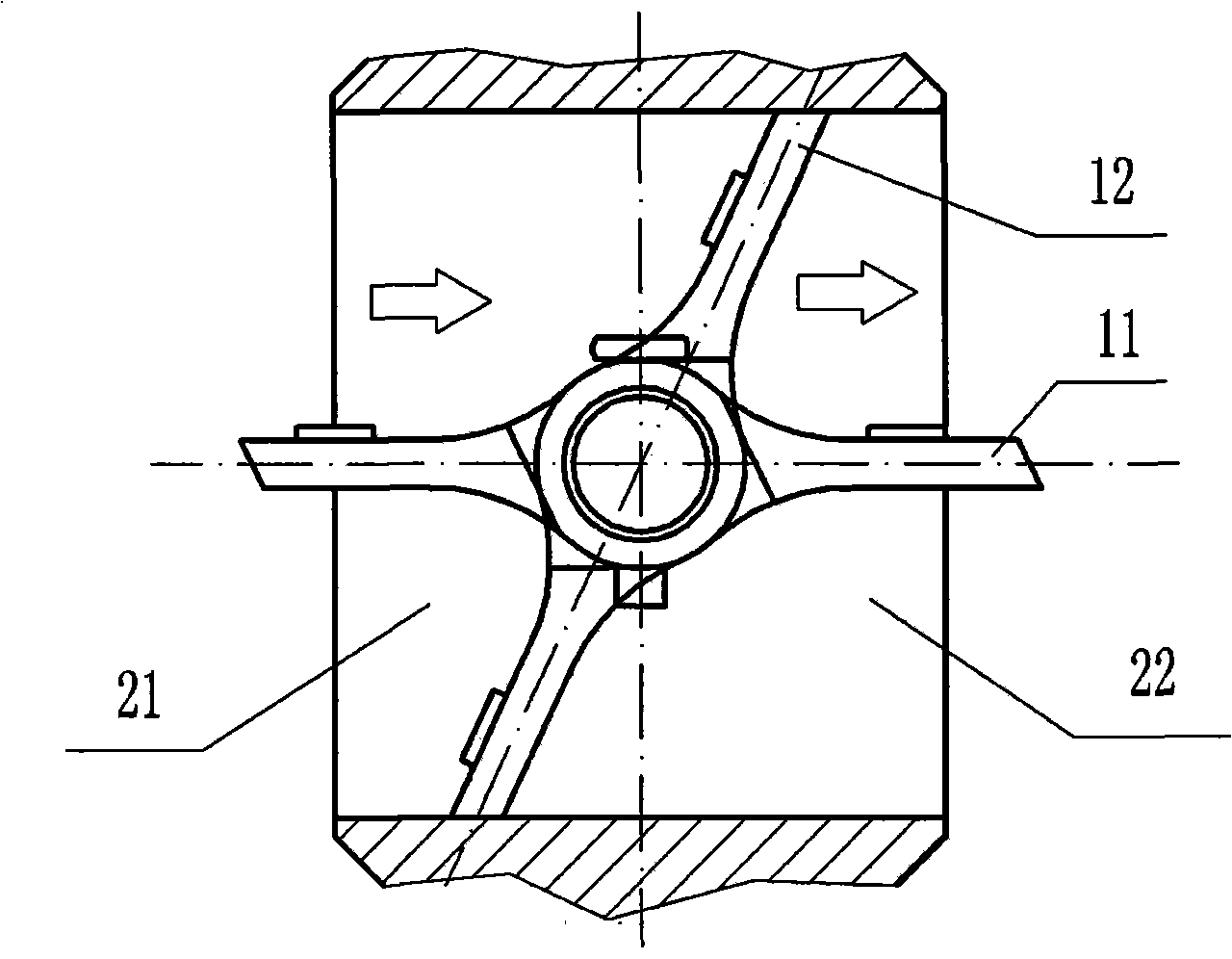
[0020] figure 1 , figure 2 The structure shown is a schematic diagram of an existing exhaust brake, and the support rod 03 fixes the disc 02 at a designated position of the valve body 01 . The direction of the arrow is the flow direction of exhaust gas. 11 indicates that the disc is in an open state, and 12 indicates that the disc is in a closed state. When the exhaust brake is working, the support rod 03 drives the disc 02 to rotate around its axis, so that the disc rotates from position 11 to position 12, thereby closing the exhaust pipe. As the exhaust gas increases, the pressure in the cavity 21 increase...


PUM


Abstract

The invention relates to an exhaust arrester capable of adjusting working pressure. The exhaust arrester comprises a valve body (01), a disk (02), a support bar (03), a support sleeve (14), a control bar (05), an air pressure feedback passage (06), a spring (07), a press plate (09), an adjusting support (10) and a cover (08); the disk (02) is fixed on an appointed position of the valve body (01) by the support bar (03) and the support sleeve (14); the support bar (03) drives the disk (2) to rotate around the axes of the disk; the control bar (05) is used for controlling connection and disconnection of an exhaust gas passage and is fixed on the bottom of the support sleeve (14) by the spring (07), the press plate (09), the adjusting support (10) and the cover (08); the air pressure feedback passage (06) drives the control bar (05) to move; and the spring (07) is used for adjusting the working pressure of an exhaust arrester assembly. When the pressure exceeds a set value by any accidental situation, the exhaust arrester can release pressure in time, ensure that the working pressure is stable and reliable and has adjustable working pressure and simple and convenient implementation.

Description

technical field [0001] The invention relates to an exhaust brake with stable and adjustable working pressure, stable braking and sensitive braking response. technical background [0002] The retarder is an auxiliary braking device for vehicles (especially heavy-duty trucks and large passenger cars). The use of auxiliary braking devices can enhance the braking performance of vehicles without using or using less main brakes (traditional friction brakes) The vehicle can be controlled within a certain safe speed range, the brake failure of the vehicle can be prevented, and the driving safety can be ensured, especially the safety when the heavy-duty vehicle goes down a long slope can be enhanced. At the same time, using the retarder can significantly reduce the frequency of use of the main service brake (friction brake), thereby reducing the wear of the main brake hub and friction plate, improving its service life, and at the same time prolonging the maintenance cycle of the main...

Claims


Application Information

Patent Timeline
Patent Type & Authority Applications(China)
IPC IPC(8): F02D13/04F01L13/06
Inventor 李瑞强
Owner 李瑞强
Why Eureka
Try Eureka