Centrifugal fan assembled guide vane vortex tongue structure

A technology of centrifugal fan and guide vane, which is applied to components of pumping devices for elastic fluids, non-variable pumps, machines/engines, etc., and can solve problems such as easy deviation of air flow and uneven outward exhaust.

Inactive Publication Date: 2008-11-19
LG ELECTRONICS (TIANJIN) APPLIANCES CO LTD
View PDF0 Cites 11 Cited by
  • Summary
  • Abstract
  • Description
  • Claims
  • Application Information

AI Technical Summary

Problems solved by technology

[0007] In addition, the airflow tends to deviate, and tends to be close to th

Method used


Image

  • Centrifugal fan assembled guide vane vortex tongue structure
  • Centrifugal fan assembled guide vane vortex tongue structure

Examples


Embodiment Construction

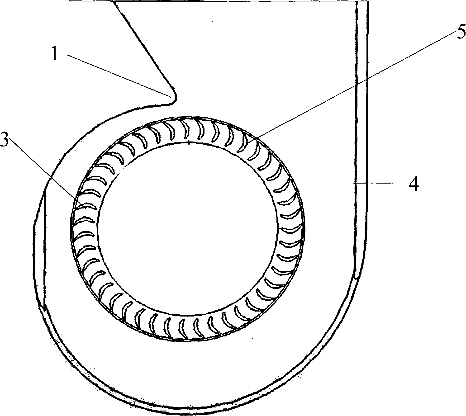
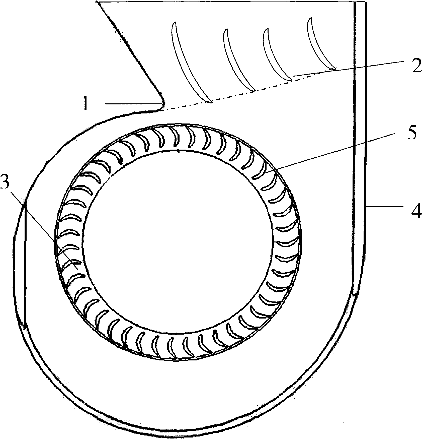
[0026] The combined guide vane vortex tongue structure of a centrifugal fan of the present invention will be further described in detail in conjunction with the accompanying drawings and specific embodiments:

[0027] Such as figure 2 As shown, in the combined guide vane volute tongue structure of the centrifugal fan of the present invention, the centrifugal fan includes a casing 4 , an impeller 3 and a volute tongue 1 . The casing 4 is made of unsaturated polyester resin and off-duty fiber. It is composed of two volutes. After the two volutes are combined and fixed and sealed, a cavity is formed. There is a spiral air duct in the cavity, which is called a collector. The gas ring is provided with an inlet or a hole in the middle of the gas collection ring, and the top of the casing 4 has an outlet, and an evaporator and other components are arranged on the upper part of the outlet, and the airflow provided by the centrifugal fan performs energy exchange in the evaporator. Th...


PUM


Abstract

The invention discloses a combined guide vanes vortex tongue structure of a centrifugal fan. The centrifugal fan is a forward fan, the front of the vortex tongue are provided with a plurality of guide vanes to assist the vortex tongue, the distance from the guide vanes and the center of an impeller is growing gradually, the front guide vanes play the role of flow guiding and wind cutting, the amount of wind cutting of the back guide vanes is small. Although the clearance between the tongue vortex and the impeller is shrinking, the noise will not increase, the angle between the bottom linked line of each guide vane and an level surface is 10 to 15 degrees, while the angle between the vortex tongue and the level surface is greater than 90 degrees, the centrifugal fan can reduce the overall size, the best angle is 100 degrees to 110 degrees, at the same time, the guide vanes are curved, and one side of a forward vortex tongue is convex, and the guide vanes can rotate a certain angle. The combined guide vanes vortex tongue structure of the centrifugal fan of the invention can reduce the noise and the size of the fan, and, at the same time, make the fan exhaust more evenly.

Description

technical field [0001] The invention relates to a centrifugal fan, in particular to a combined guide vane volute tongue structure of the centrifugal fan. Background technique [0002] Most of the centrifugal fans in the prior art are backward, that is, the bending direction of the blades is opposite to the direction of the airflow. This kind of centrifugal fan has a very obvious feature, that is, the air volume is large, but the static pressure is small. There are many resistance parts in the centrifugal fan, including evaporator, electric heater and volute, etc. The resistance parts form resistance to the airflow in the centrifugal fan, so it is necessary to rely on static pressure to overcome the resistance. The effective way to overcome the static pressure resistance is to Swap the forward facing centrifugal fan for a forward facing centrifugal fan. The forward centrifugal fan refers to the centrifugal fan whose blades are bent in the same direction as the airflow. The f...

Claims


Application Information

Patent Timeline
IPC IPC(8): F04D29/46
Inventor 王雷
Owner LG ELECTRONICS (TIANJIN) APPLIANCES CO LTD
Why Eureka
Try Eureka