
Illuminating device of LED light source oppositely shooting light guider possessing fluorescent lamp effect

A technology of LED light source and light-emitting device, applied in the direction of light guide, light source, point light source, etc., can solve the problems of low brightness, high energy consumption of LED light source, restricted use, etc., so as to solve the technical bottleneck problem, reduce energy consumption, and improve brightness Effect

Inactive Publication Date: 2008-11-19
东莞市星锐灯饰有限公司
View PDF0 Cites 3 Cited by
  • Summary
  • Abstract
  • Description
  • Claims
  • Application Information

AI Technical Summary

Problems solved by technology

However, these earlier lighting technology solutions have many disadvantages. The life of incandescent lamps or fluorescent lamps is short, the production process pollutes the environment, and the energy consumption is relatively large compared with LED light sources. It can be used in auxiliary lighting. When used in the lighting industry, it cannot be widely used in the lighting industry due to the low brightness of the lighting.
[0003] In addition, because the LED light source is a cold light source, it has the advantages of no pollution, long service life, low energy consumption, and environmental protection, so it has a wide application prospect in the lighting industry. It cannot meet the needs of the national energy conservation and environmental protection policy

Method used


Image

  • Illuminating device of LED light source oppositely shooting light guider possessing fluorescent lamp effect
  • Illuminating device of LED light source oppositely shooting light guider possessing fluorescent lamp effect
  • Illuminating device of LED light source oppositely shooting light guider possessing fluorescent lamp effect

Examples


Embodiment Construction

[0013] The following is the best example of a light-emitting device with a fluorescent lamp effect by using an LED light source to illuminate a light guide in the present invention, which does not limit the protection scope of the present invention.

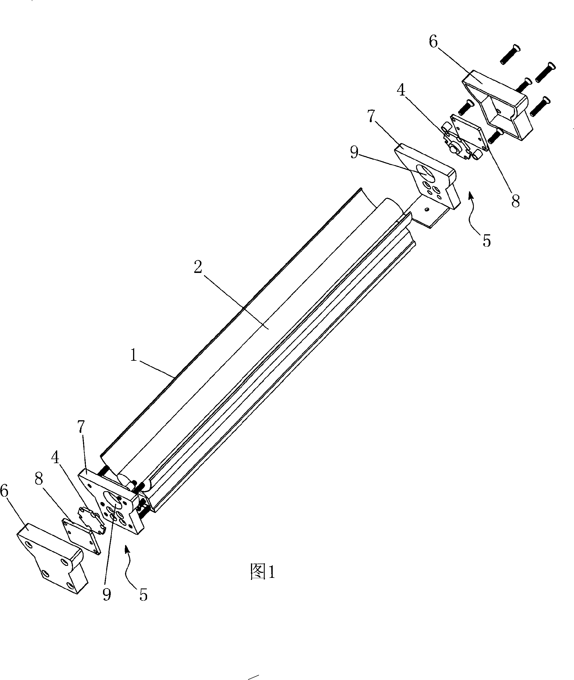
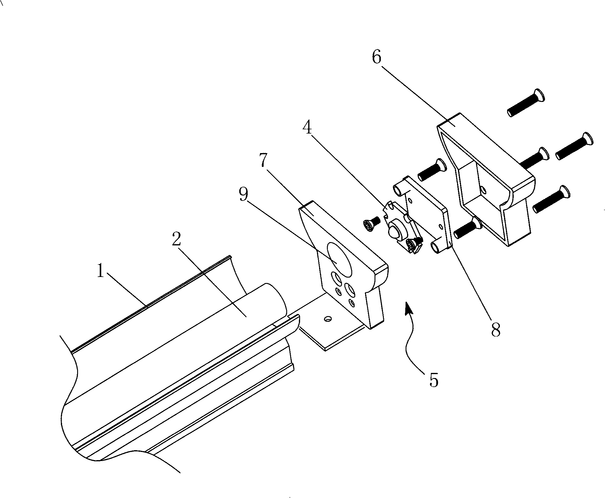
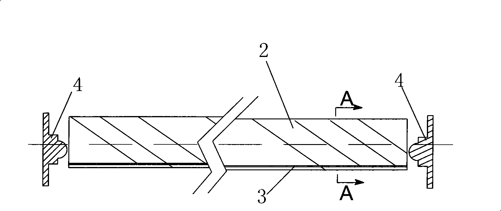
[0014] Referring to Figure 1, figure 2 , image 3 , Figure 4 , to provide a light-emitting device with a fluorescent lamp effect by using an LED light source to illuminate a light guide body, including a lamp body 1, and at least one light guide body 2 installed in the lamp body 1, and the inside of the light guide body 2 is axially A reflective strip 3 parallel to the axis of the light guide body 2 is installed, and at least one LED light source 4 facing each other is arranged symmetrically at both ends of the light guide body 2. The LED light source 4 is installed at the end of the lamp body 1. The LED light source 4 The projection on the side of the light guide 2 is located between the reflective strip 2 and the cross-secti...


PUM


Abstract

The invention discloses a light-emitting device capable of achieving a fluorescent lamp effect by oppositely irradiating a light guide with LED light sources, which comprises a lamp body and at least one light guide arranged in the lamp body. A reflecting strip which is parallel to the axis of the light guide is arranged in the light guide along the axial direction, at least one pair of oppositely irradiating LED light source is arranged on the two ends of the light guide, the LED light source is arranged on the front end of the lamp body, the projection of the LED light source on the side of the light guide is between the reflecting strip and a cross section along the axis of the light guide. The light rays emitted by the oppositely irradiating LED light sources are projected onto the light guide, the reflecting strip in the light guide reflects the light rays from the LED light source in the light guide, increases the brightness of the light guide, achieves the effect of a fluorescent lamp, solves technology bottleneck problem of the application of LED light sources in the lighting industry, contributes to the wide applications of the LED light source in the lighting industry, has the advantages of no pollution, on glare, long service life, low energy consumption, energy conservation and environmental protection.

Description

Technical field [0001] The present invention relates to an illuminating device, more specifically, to a lighting device in which an LED light source illuminates a light guide body and has the effect of a fluorescent lamp. technical background [0002] Most of the traditional lighting industry uses incandescent lamps, fluorescent lamps (fluorescent lamps), etc. as the main lighting equipment. However, these earlier lighting technology solutions have many disadvantages. The life of incandescent lamps or fluorescent lamps is short, the production process pollutes the environment, and the energy consumption is relatively large compared with LED light sources. It can be used in auxiliary lighting, but when it is used in the lighting industry, it cannot be widely used in the lighting industry because of the low brightness of the lighting. [0003] In addition, because the LED light source is a cold light source, it has the advantages of no pollution, long service life, low energy...

Claims


Application Information

Patent Timeline
Patent Type & Authority Applications(China)
IPC IPC(8): F21V13/02F21V8/00F21V7/00F21V19/00F21Y101/02F21Y115/10
Inventor 康文杰
Owner 东莞市星锐灯饰有限公司
Learn More