
Medium insulation properties measuring apparatus for gas-liquid two-phase fluid state

A technology of gas-liquid two-phase flow and insulation performance, applied in the direction of testing dielectric strength, etc., can solve the problems of inability to measure fluorocarbons, inability to achieve gas sealing, and inability to measure fluorocarbon media

Active Publication Date: 2008-11-19
INST OF ELECTRICAL ENG CHINESE ACAD OF SCI +1
View PDF1 Cites 27 Cited by
  • Summary
  • Abstract
  • Description
  • Claims
  • Application Information

AI Technical Summary

Problems solved by technology

[0006] After research and retrieval, it is found that in order to measure the insulation properties of insulating liquids at different temperatures, many test occasions use non-standard containers, which can heat the liquid in the container, but cannot be gas-tight.
For example, the utility model of the "liquid insulation measuring device" with the patent number of 93245356.2 is to improve the existing three-terminal electrode cup, so that the inside and outside can be heated at the same time, the temperature is uniform and the heating is rapid, but the gas seal cannot be guaranteed.
That is to say, the existing measuring devices for insulation performance can only measure the liquid or gas medium in the device statically, and cannot be heated; or they are not sealed, and cannot effectively measure the volatile fluorocarbon medium
Ineffective measurement of volatile fluorocarbons
[0007] Searching other domestic and foreign patent documents, except for the above-mentioned patents, are all aimed at the measurement method of certain insulation properties such as breakdown performance and partial discharge performance, or the improvement of the measurement device based on a certain measurement method, but none of them have been carried out. Start with the demand for insulation performance measurement under two-phase flow state, improve or make a measurement device

Method used


Image

  • Medium insulation properties measuring apparatus for gas-liquid two-phase fluid state
  • Medium insulation properties measuring apparatus for gas-liquid two-phase fluid state
  • Medium insulation properties measuring apparatus for gas-liquid two-phase fluid state

Examples


Embodiment Construction

[0024] The present invention will be further described below in conjunction with the accompanying drawings and specific embodiments.

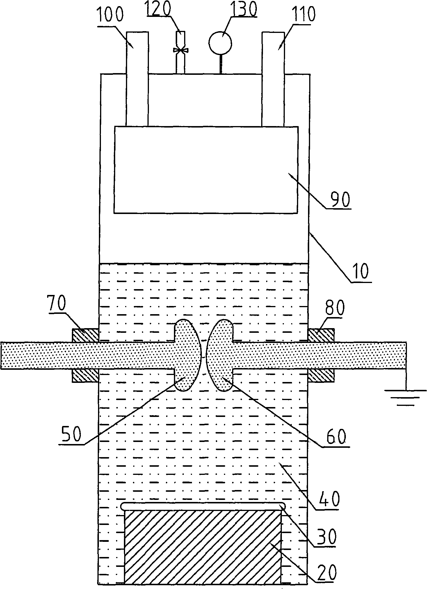
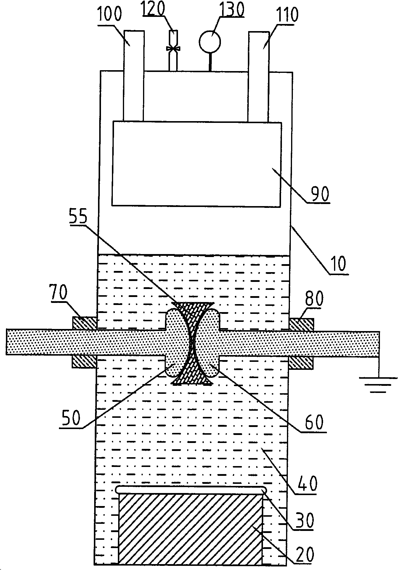
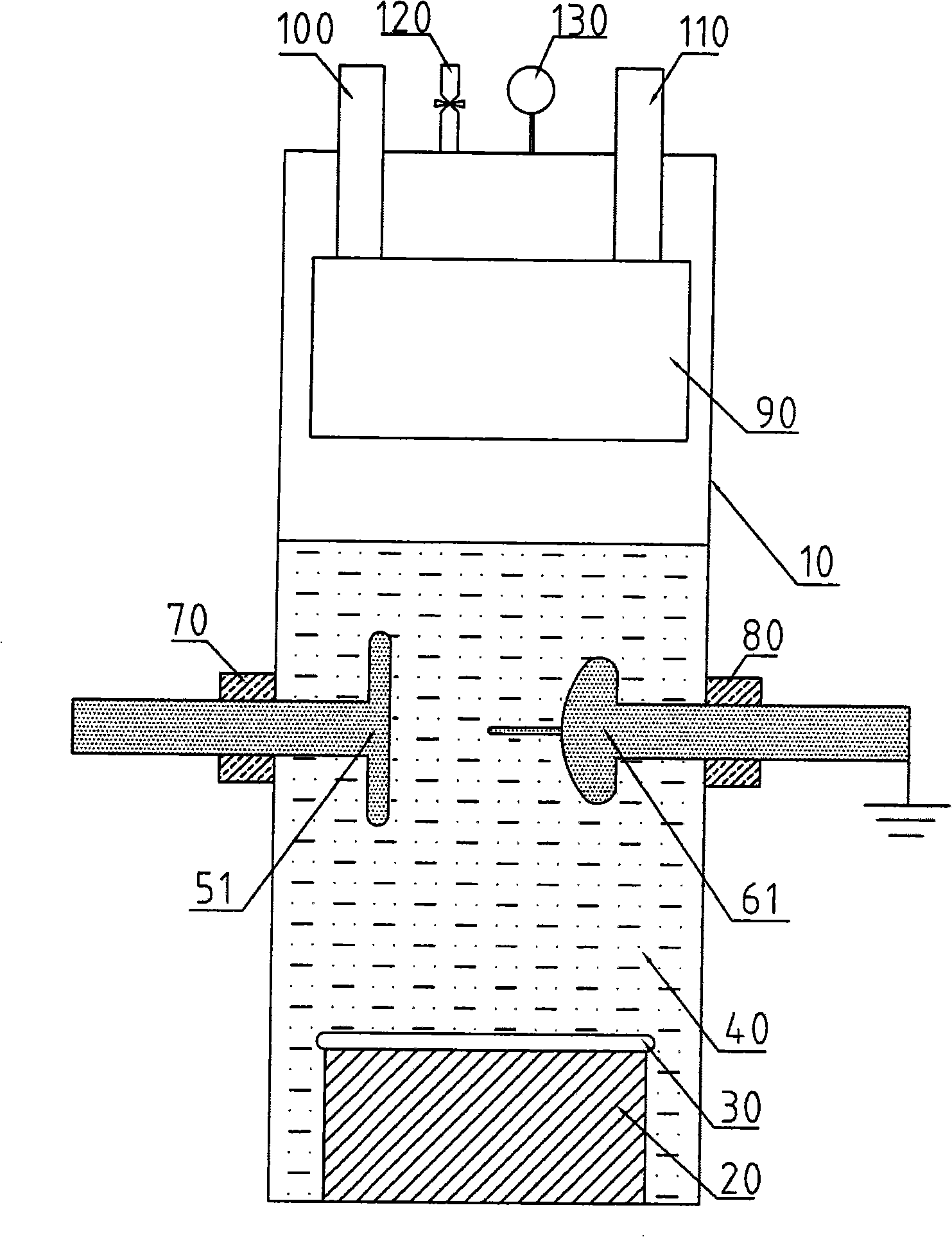
[0025] like figure 1 As shown, one of the specific embodiments of the present invention consists of a sealed container 10, a heating device 20, a liquid medium 40 to be measured, a high-voltage electrode 50, a low-voltage electrode 60, a high-voltage electrode sealing device 70, a low-voltage electrode sealing device 80, a condensation device 90, and a valve 120 and pressure measuring instrument 130 etc. composition. The heating device 20 is located at the bottom of the sealed container 10 and heats the liquid medium 40 to be tested poured into the sealed container. The vapor generated after the liquid medium 40 to be tested boils and evaporates is condensed by the condensing device 90 on the upper part of the sealed container 10 , becomes liquid again, and flows back to the bottom of the sealed container 10 . The condensing device 90 is a ho...


PUM


Abstract

Disclosed is an apparatus used for measuring medium insulating property in the gas-liquid phase flow state, a heating device (20) is positioned at the bottom part of an airtight container (10), and a condensing device (90) is positioned at the upper part of the airtight container (10). The condensing device (90) is provided with a water inlet (100) and a water outlet (110) penetrating through the top plate of the airtight container (10). A high voltage electrode (50) and a low voltage electrode (60) are positioned at the middle part of the airtight container (10), and penetrate into the airtight container (10) from two relative directions; and a liquid medium (40) under test is added into the airtight container (10), the heating device (20) heats the liquid medium (40) to boil in the two-phase flow state, the steam generated by the liquid medium (40) after boiling evaporation is cooled by the condensing device (90) to turn into liquid and flow back to the bottom part of the airtight container (10). The apparatus can be used for measuring insulating properties of various liquid media and solid insulation materials in the liquid medium environment under the gas-liquid phase flow state.

Description

technical field [0001] The invention relates to a device for measuring high-voltage insulation performance, in particular to a device for measuring dielectric insulation performance in the state of gas-liquid two-phase flow. Background technique [0002] Some non-combustible fluorocarbons can be used as insulating and cooling media for various electrical equipment including power transformers due to their good insulating and cooling properties. The electrical equipment using this technology has the characteristics of small size, light weight, non-flammable, non-explosive, safe and reliable, green and environmental protection, etc. It can meet the growing demand for high-voltage and large-capacity urban power grids, and is especially suitable for power loads such as urban center substations. Dense areas, high-rise buildings and other places where the installation space is relatively narrow and the fire protection requirements are relatively high. [0003] When non-combustibl...

Claims


Application Information

Patent Timeline
IPC IPC(8): G01R31/12
Inventor 牛文豪张国强王新
Owner INST OF ELECTRICAL ENG CHINESE ACAD OF SCI
Learn More