Elevator system

A technology for elevators and elevator cars, which is applied to elevators, textile cables, hoisting devices, etc. in buildings. The effect of increased tensile strength

Inactive Publication Date: 2008-11-19
KONE CORP
View PDF1 Cites 3 Cited by
  • Summary
  • Abstract
  • Description
  • Claims
  • Application Information

AI Technical Summary

Problems solved by technology

In the solution described, half of the strands are cut off, as a result the tensile strength of the rope is reduced, and this method additionally requires the use of a cable to pull the sleeve, which increases the thickness of the spliced ​​section

Method used


Image

  • Elevator system
  • Elevator system
  • Elevator system

Examples


Embodiment Construction

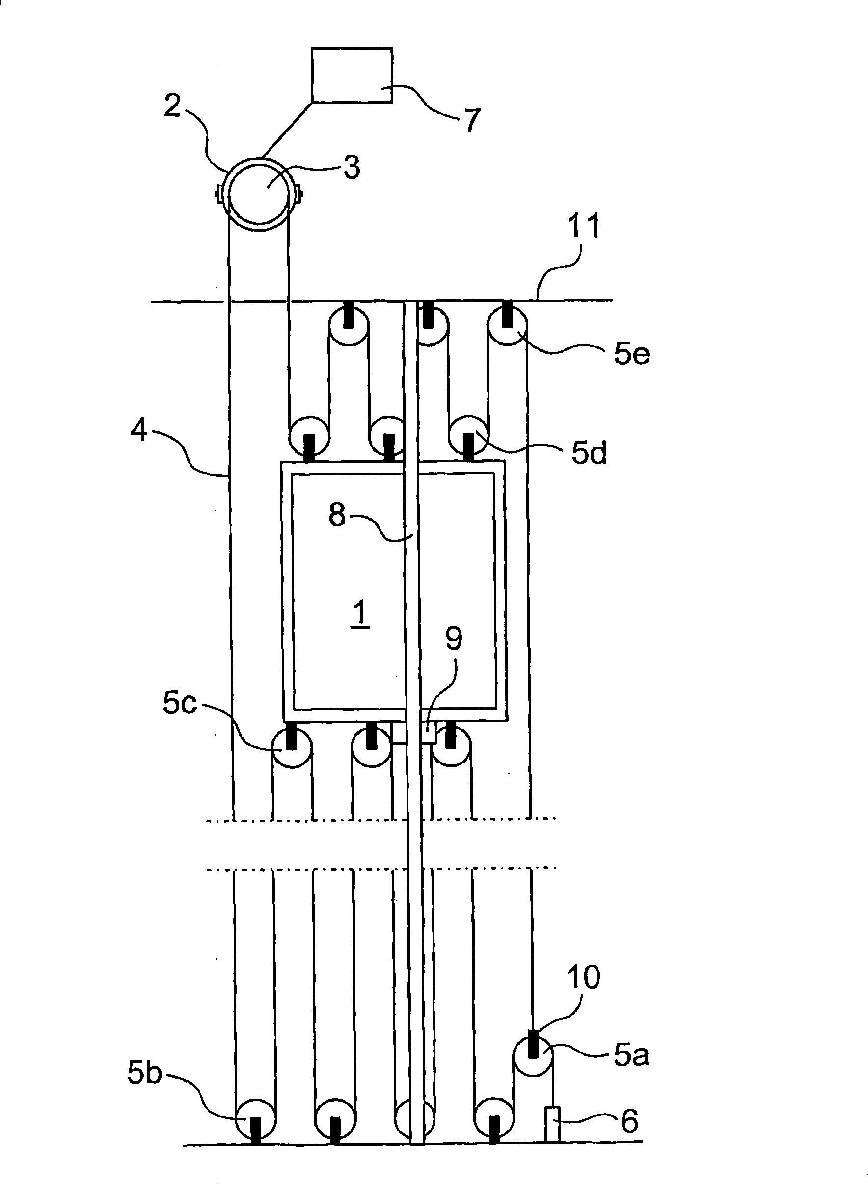
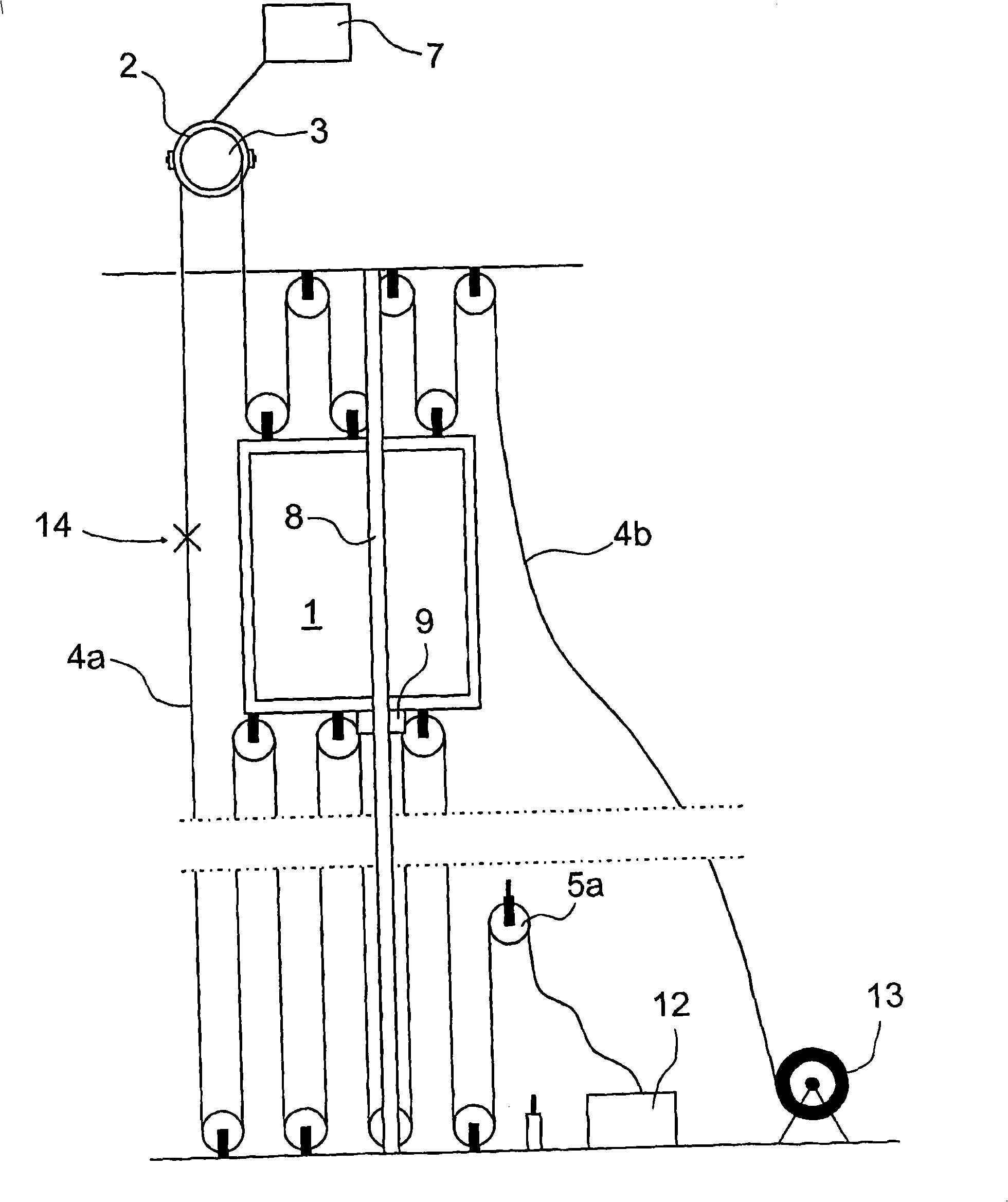
[0019] figure 1 shows a typical traction sheave elevator without counterweight provided with a set of ropes, such as traction rope 4, in which the method of the present invention for changing a set of traction ropes can be applied. The elevator car 1 is suspended by the set of hoisting ropes 4 and runs up and down in the elevator shaft along the guide rails 8 substantially in the vertical direction. The hoisting power of the elevator is provided by the traction machine 2, and the traction machine is connected to the control system 7 of the elevator. The first end of the set of traction ropes 4 is fixed to the anchor piece 6 fixed at the lower part of the elevator shaft, from which the traction ropes are guided, and first go around the ropes placed above the bottom of the elevator shaft from above Force compensation sheave 5a, then walk around the diverting pulley 5b that is installed at the bottom of the elevator hoistway from below, and the rope walks around the diverting pu...


PUM

PropertyMeasurementUnit
lengthaaaaaaaaaa
diameteraaaaaaaaaa

Abstract

The invention relates to a method for replacing the hoisting ropes of an elevator. By the method of the invention, the hoisting ropes (4) are replaced by first joining the old and new hoisting ropes (4a, 4b) together by their one ends by splicing the ends together around a common core strand (17), whereupon the new set (4b) of hoisting ropes is pulled into place by means of the old set (4a) of hoisting ropes.

Description

technical field [0001] The invention relates to a method for replacing elevator ropes according to the preamble of claim 1 . Background technique [0002] Elevator safety regulations require that the hoisting ropes of a rope elevator should be replaced periodically with a new set of hoisting ropes, since the ropes are subject to wear during use and can break after excessive wear. In the prior art, the traction rope has been replaced by first removing the old rope and then putting the new rope in place. The disadvantage of this solution is that changing the rope by this method is a slow and difficult process that takes a lot of time. Especially in the case of elevators without counterweight, the elevator has a large suspension ratio, for example in the range of 4:1-12:1, with this traditional method of replacing the ropes, due to the many deflection pulleys, Often a very laborious and slow operation, and not always safe. [0003] A prior art method for replacing elevator r...

Claims


Application Information

Patent Timeline
Patent Type & Authority Applications(China)
IPC IPC(8): B66B19/02F16G11/08B66B
CPCB66B19/02Y10T29/49734Y10T29/4973Y10T29/49815B66B11/007Y10T29/49947D07B7/165D07B2501/2007D07B7/169B66B7/00B66B7/06
Inventor 马蒂·海恩尼安西·卡皮南阿托·特基奥
Owner KONE CORP
Why Eureka
Try Eureka