Installation for high pressure compression with several stages

一种高压压缩、压缩设备的技术,应用在多级泵、机械设备、液体燃料发动机等方向,能够解决气体消耗、压缩设备成本高、增加压缩设备体积等问题,达到气体数量减少、小成本的效果

Active Publication Date: 2011-07-20
ATLAS COPCO CREPELLE
View PDF4 Cites 0 Cited by
  • Summary
  • Abstract
  • Description
  • Claims
  • Application Information

AI Technical Summary

Problems solved by technology

Another disadvantage of [0011] known multi-stage compressors is that the first accumulator between the two compressors is relatively large in case When the booster compressor is loaded, the gas filled in the first storage is completely consumed before the first compressor is loaded
[0012] Apparently, a large reservoir of this type pre-installed between the compressors increases the volume of the compression equipment, in fact making the compression Equipment costs are also higher

Method used


Image

  • Installation for high pressure compression with several stages
  • Installation for high pressure compression with several stages
  • Installation for high pressure compression with several stages

Examples


Embodiment Construction

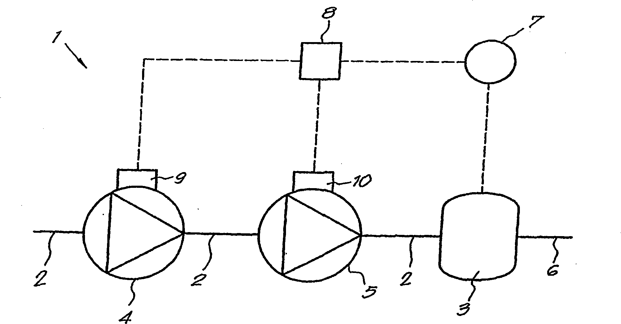
[0024] Such as figure 1 As shown, a multistage high-pressure compression plant 1 according to the invention essentially comprises a main gas line 2 leading to a buffer 3, in this case two volumetric compressors 4 and 5 installed in series In the pipeline 2.

[0025] The first compressor 4 is for example a screw compressor (compresseur à vis) for the low-pressure compression stage, while the second compressor 5 - also called booster compressor - is for example a piston compressor, It is used in high pressure compression stages.

[0026] The aforementioned buffer 3 may be a storage or similar connected to the user network 6, and preferably provided therein is a component 7 that makes it possible to determine the gas pressure of the filling in said storage, and said component 7 is connected to a control box 8, which is, for example, an electronics box.

[0027] Of course, the above-mentioned means 7 designed to determine the pressure can, if desired, also be installed at the ...


PUM


Abstract

The invention concerns an installation for high pressure compression with several stages, normally used for producing PET bottles. The inventive installation comprises a main pipe (2) emerging in a baffle plate (3), wherein at least two compressors (4, 5) are mounted in series each having its own drive member (9, 10). The installation is equipped with means (7) for determining the pressure at theoutput of the main pipe (2), said installation being connected to a control box (8). Typically, the control box (8) is connected to at least two of the drive members (9, 10) of the compressors (4, 5)and ensures monitoring of said compressors such that the latter rotate jointly whether charged or uncharged. Thus, the compressors (4, 5) are jointly charged based on the pressure prevailing in the baffle plate (3), such that the charging of the compressor representing the overpressure stage, the compressor(s) of the lower compression stages are automatically and jointly charged.

Description

technical field [0001] The invention relates to a multi-stage high-pressure compression device comprising at least two compressors connected in series by a pipeline. Background technique [0002] High-pressure equipment of this type is used, for example, in the field of production of polyethylene terephthalate (PET) bottles, which require the use of compressed gas at pressures in excess of 2000 kPa. [0003] It is known, in order to achieve a gas pressure of 2000 kPa or more, to install two volumetric compressors in series, and to presuppose a first gas reservoir at the outlet of the first compressor, the outlet of said reservoir being connected to the The inlet of the second compressor is connected, said second compressor is a booster compressor. [0004] At the outlet of the above-mentioned booster compressor, it is generally preferred to preset a second storage, which acts as a buffer for the user network. [0005] In known multistage compressors of this type, the drive...

Claims


Application Information

Patent Timeline
Patent Type & Authority Patents(China)
IPC IPC(8): F04B41/02F04C23/00F04B41/06
CPCF04B41/06F04C23/005F04C28/08F04B49/065F04B41/02F04C2270/56F04C28/02F04C23/001F04C18/16F04B25/00F04B2205/05F04C2270/18
Inventor P·M·A·勒隆H·T·马吉茨
Owner ATLAS COPCO CREPELLE
Why Eureka
Try Eureka