Reaction kettle bottom agitation system

A reaction kettle and bottom stirring technology, applied in the field of homogenization, shearing and emulsification, can solve the problems of increased weight, processing cost, and excessively long stirring shaft, and achieve the effect of shortened length, stable operation and efficient shearing

Active Publication Date: 2008-11-26
合肥华升泵阀股份有限公司
View PDF0 Cites 11 Cited by
  • Summary
  • Abstract
  • Description
  • Claims
  • Application Information

AI Technical Summary

Problems solved by technology

For large-scale reactors, most of them adopt the vertical installation method. In the prior art, the top-entry structure is mostly used. In this top-entry structure, the stirring shaft needs to extend from the top of the kettle to the bottom of the kettle, so there is a stirring shaft The problem of too long, and too long agitator shaft will cause many problems, such as in order to ensure the torsional strength of the agitator shaft, it is necessary to increase the diameter of the shaft, and the thicker the diameter of the shaft, the support must be strengthened, which will increase the weight, processing costs, etc.

Method used


Image

  • Reaction kettle bottom agitation system
  • Reaction kettle bottom agitation system

Examples


Embodiment Construction

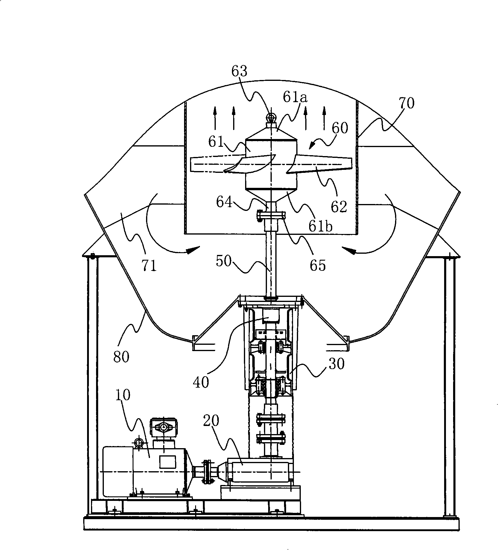
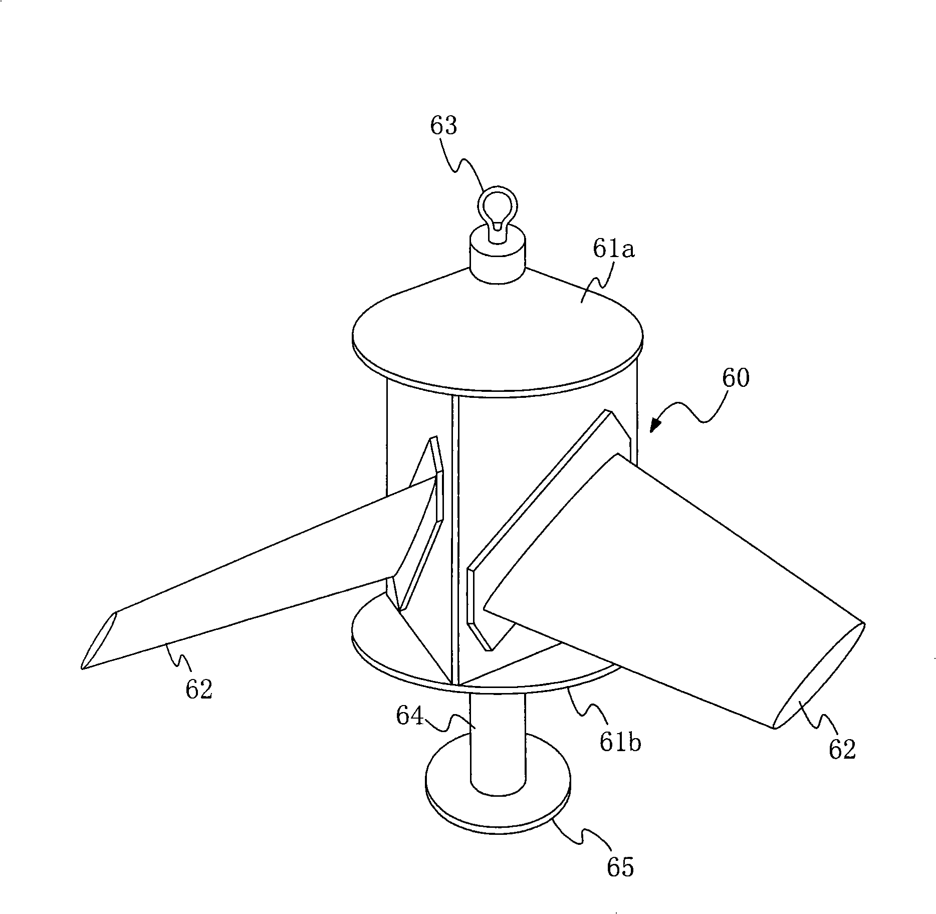
[0008] see figure 1 , the stirring system at the bottom of the reaction kettle includes that the interior of the reaction kettle 80 is equipped with a shroud 70, the upper and lower ends of the shroud 70 are open, the stirring device 60 is located in the shroud 70, and the lower part of the stirring device 60 has a transmission device 30 fixed on it. At the bottom of the reaction kettle 80, a cartridge type combined mechanical seal 40 is arranged between the transmission device 30 and the bottom of the reaction kettle 80, the transmission device 30 is connected with the power output shaft of the reducer 20, and the reducer 20 The power input shaft is connected with the motor 10 .

[0009] The invention is suitable for the axial-flow wing-type blade type and the assembled combined mechanical seal bottom stirring device of various reactors, and is used for the reactor stirring system with the bottom stirring structure. The cartridge combined mechanical seal 40 is installed at t...


PUM


Abstract

The invention discloses a stirring system at the bottom of a reaction kettle, which can be widely applied to the processes of shearing, emulsification and homogenizing in media of petroleum trade, chemical industry, pharmaceuticals industry, food service industry, etc. The reaction kettle is internally provided with an air guide sleeve the upper end and the lower end of which are both open. The lower part of a stirring device in the air guide sleeve is provided with a transmission device which is fixed at the bottom of the reaction kettle. Cartridge and combined mechanical seals are arranged between the bottoms of the transmission device and the reaction kettle, and the transmission device is connected with a power output shaft of a speed reducer while a power input shaft of the speed reducer is connected with a motor. With the respect to the problem of the over-length of stirring shafts in the general jacking structure adopted, the stirring system of the invention can greatly shorten the length of the stirring shaft and ensure the stable operation and that a rotating shaft bears small subsidiary stress, thus providing comparatively favorable application environment for sealing.

Description

technical field [0001] The invention can be widely used in the processes of shearing, emulsification and homogenization of media in industries such as petroleum, chemical industry, medicine and food. Background technique [0002] With the development of modern industry, chemical equipment is gradually becoming large-scale, and the reaction kettle is also showing a trend of large-scale. For large-scale reactors, most of them are installed vertically. In the prior art, the top-entry structure is mostly used. In this top-entry structure, the stirring shaft needs to extend from the top of the kettle to the bottom of the kettle, so there is a stirring shaft The problem of too long, and too long agitator shaft will cause many problems. For example, in order to ensure the torsional strength of the agitator shaft, the shaft diameter needs to be thickened. If the shaft diameter is thickened, the support must be strengthened, which will increase the weight and processing costs. Cont...

Claims


Application Information

Patent Timeline
Patent Type & Authority Applications(China)
IPC IPC(8): B01F7/18B01J19/18
Inventor 巫建波何玉杰李强柴立平程道武姜漫朱维虎
Owner 合肥华升泵阀股份有限公司
Why Eureka
Try Eureka