Formwork component forming mold

A formwork component and forming mold technology, which is applied in the direction of formwork/formwork components, building components, formwork/formwork/work frame connectors, etc., can solve the problem of easy damage and detachment of open thin-walled tubes or thin-walled boxes. Problems such as inconvenient mold

Inactive Publication Date: 2008-11-26
邱则有
View PDF2 Cites 1 Cited by
  • Summary
  • Abstract
  • Description
  • Claims
  • Application Information

AI Technical Summary

Problems solved by technology

Such as the female mold, as can be seen from their drawings, it includes a side mold surface and a bottom mold surface, and the side mold surface and the bottom mold surface form a female mold. This kind of female mold is the female mold of the overall template. Among them, demoulding is inconvenient, and the open thin-walled tube or thin-walled box is easily damaged. Therefore, it is urgently needed to develop a new type of mold for forming shell components.

Method used


Image

  • Formwork component forming mold
  • Formwork component forming mold
  • Formwork component forming mold

Examples


Embodiment Construction

[0069] The present invention will be further described below in conjunction with the accompanying drawings and embodiments.

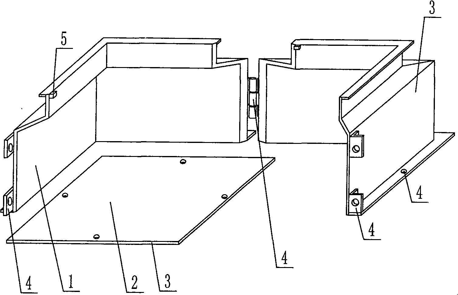
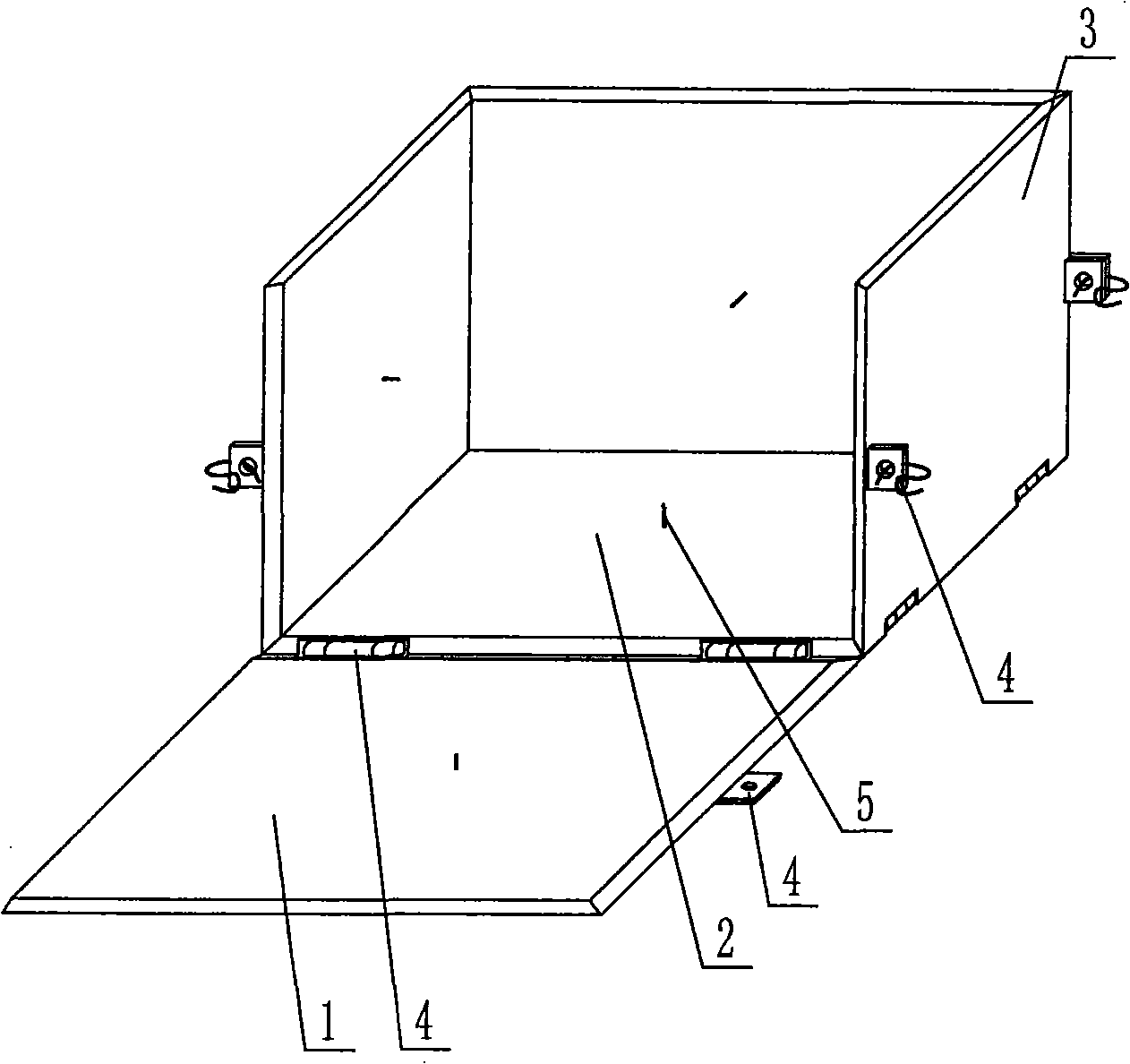
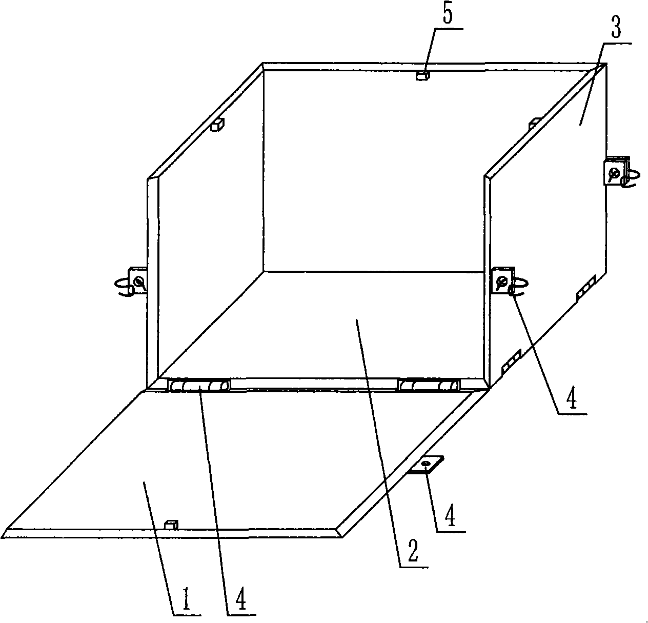
[0070] As shown in the accompanying drawings, the present invention comprises a side mold surface 1 and a bottom mold surface 2, and the side mold surface 1 and the bottom mold surface 2 surround a female mold, and is characterized in that the side mold surface 1 and the bottom mold surface of the female mold 2 is composed of a template 3, the female mold is composed of at least two templates 3, a splicing device 4 is arranged on the combined template 3, a mold shell thickness limiting device 5 is arranged on the template 3, and there is at least one gap on the template 3, At least one formwork 3 is a disposable formwork serving as part of the formwork member. Fig. 1 is a schematic structural diagram of Embodiment 1 of the present invention. In each accompanying drawing, 1 is a side mold surface, 2 is a bottom mold surface, 3 is a template, 4 is a spli...


PUM


Abstract

A shaping die of a die shell component includes a side die surface (1) and a bottom die surface (2); a female die is enclosed by the side die surface (1) and the bottom die surface (2). The invention is characterized in that the side die surface (1) and the bottom die surface (2) of the female die consist of templates (3); the female die is jointed and combined by at least two templates (3); a split unit(4) is arranged on the jointed templates (3); a die shell thickness limitation device (5) is arranged on the templates (3); at least one gap (15) is arranged on the templates (3); at least one template (3) is a one-off template which is taken as the part of the die shell component. In this way, after the templates are provided with the gap, the templates are very convenient for arranging and positioning reinforcements such as reinforcing steel bars, steel wires, and the like, and are beneficial to improving the manufacture efficiency; besides, the die is also characterized by simple structure, easy manufacture, high intensity, low cost, and the like, is applicable to manufacturing thin-walled tubes or thin-walled boxes and is applicable to manufacturing ringent thin-walled tubes or thin-walled boxes in particular.

Description

[0001] This application is a divisional application of the invention patent application with the filing date of January 20, 2004, the application number of 200410002653.X, and the title of "a mold for molding shell components". (1) Technical field [0002] The invention relates to a mold for molding shell components. (2) Background technology [0003] At present, cast-in-place reinforced concrete hollow slabs, especially the non-core-pulling hole-forming process of cast-in-situ reinforced concrete hollow slabs, are generally filled with thin-walled tubes or thin-walled boxes, which can meet the needs of various hollow slabs for evacuating concrete. The applicant applied for an invention patent with the application number 99115665.X and the title "fiber-reinforced thin-walled pipe (box) for reinforced concrete filling and its manufacturing method" on November 29, 1999, and the application number 99115666.8 , the invention patent titled "fiber-reinforced thin-walled box for fi...

Claims


Application Information

Patent Timeline
IPC IPC(8): E04G9/08E04G17/00E04B5/16
Inventor 邱则有
Owner 邱则有
Why Eureka
Try Eureka