High voltage power source of resonant transformer

A technology of resonant converter and high-voltage power supply, which is applied to output power conversion devices, instruments, and DC power input to DC power output. , to achieve the effect of high overall performance

Inactive Publication Date: 2008-11-26
合肥雷科电子科技有限公司
View PDF0 Cites 28 Cited by
  • Summary
  • Abstract
  • Description
  • Claims
  • Application Information

AI Technical Summary

Problems solved by technology

[0004] In view of the above problems, the purpose of the present invention is to solve the problems in the prior art that the peak current flowing throu

Method used


Image

  • High voltage power source of resonant transformer
  • High voltage power source of resonant transformer
  • High voltage power source of resonant transformer

Examples


Embodiment 1

[0038] This example is a power supply device with an output of 1kW, which does not have an active power factor correction circuit 1 and is directly powered by 220V mains. The form of the resonant circuit is a half-bridge, the minimum operating frequency is selected as 40kHz, and the maximum operating frequency is 100kHz. Circuit structure see Figure 6 , the resonant current waveform see Figure 7, the theoretical analysis is as above. The AC 220V mains input rectifier filter circuit 1 ′ provides a DC 300V voltage after passing through the rectifier bridge 11 and filter capacitors 121 and 122 , which is used for the input voltage of the resonant circuit 2 . The switch tubes 211, 212 are connected in parallel with diodes 221, 222, where the diodes are used as freewheeling diodes to form a switch tube assembly, and the two switch tube assemblies are connected in series. Two sets of switching tube components in series and two capacitors 231 and 232 in series are connected in p...

Embodiment 2

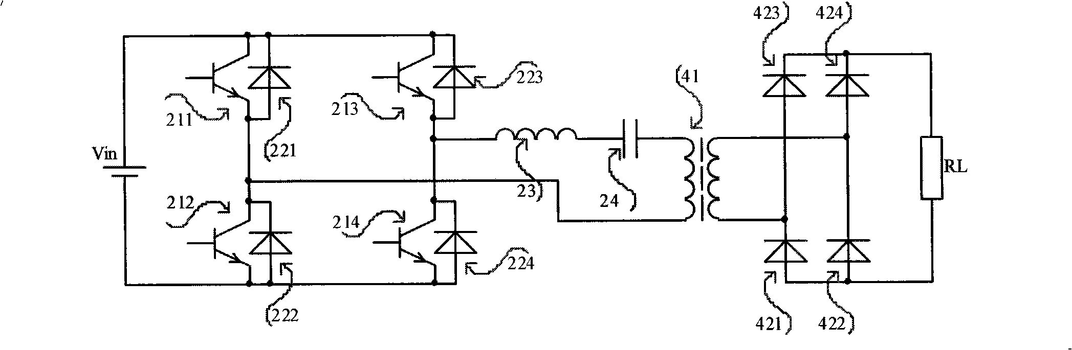
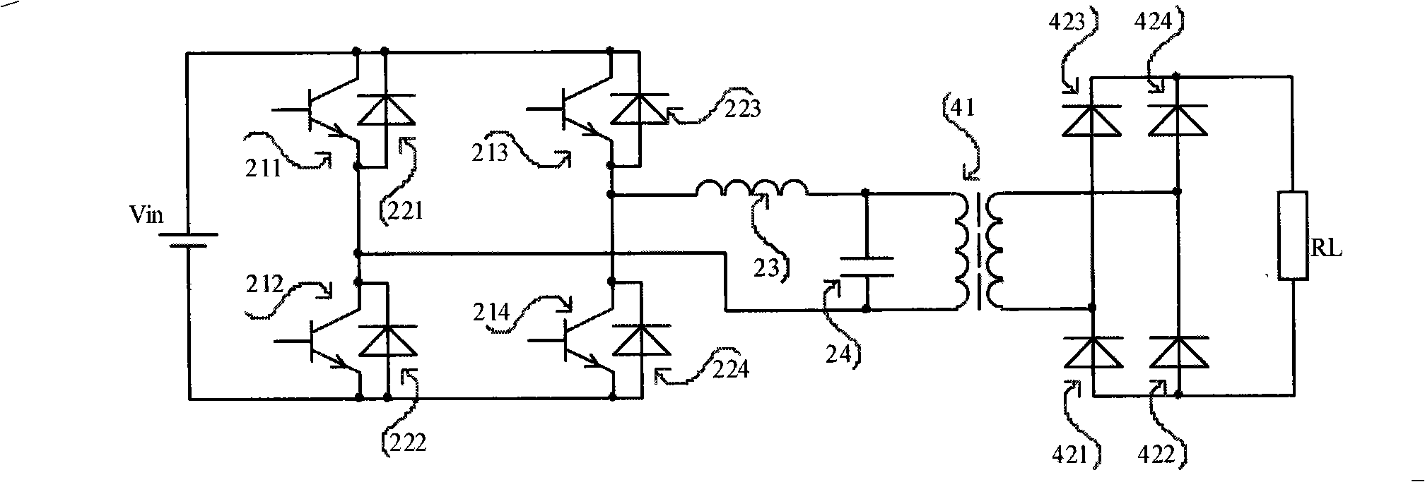
[0044] This example is an output 2kW power supply device, which is equipped with an active power factor correction circuit 1, which converts the mains 220V power supply into a DC 390V voltage, and provides it to the resonant circuit 2 of the rear stage. The form of the resonant circuit is a full bridge, the minimum operating frequency is selected as 40kHz, and the maximum operating frequency is 100kHz. Circuit structure such as Figure 8 shown.

[0045] The AC 220V input is rectified by diodes 111-114 to obtain a half-sine wave. Such a half sine wave is added to the input end of the high-frequency inductance correction circuit 1, and at the same time added to the control circuit 3 for processing as a reference signal to determine the required phase and waveform of the input current. The input current passes through the inductor 12 and returns through the current detecting resistor 13 , and provides the sampling value of the actual current waveform to the control circuit 3 . ...


PUM


Abstract

The invention relates to a high-pressure power supply device of a resonant converter, which mainly resolves problems that in the prior art, the peak value of electric current which passes through switching tubes is high, the control of the power supply is complicated, and operation under the direct current stabilized output state is not easy to realized. The high-pressure power supply device employs a parallel resonant topology structured circuit, and a resonant capacitor is in primary and parallel connection with a transformer. The circuit structure can be used in full bridge or half-bridge type, can be connected with an input end of an active power factor correct circuit, and also can directly employ commercial power 220V to supply power. The high-pressure power supply device can meet the mode that high-pressure power supply is applied to the direct current stabilized output state and a capacitance constant-current charge state, and can be suitable for the occasion of power supply load changing suddenly, and by combining the advantages of a resonant converter and a pulse-frequency modulating (PFM) transformer, the performance of the whole device can achieve extremely high power density.

Description

technical field [0001] The invention relates to a power supply device, in particular to a high-voltage power supply device for a resonant converter. Background technique [0002] Power electronics technology has developed rapidly in recent years. With the development of communication technology and power system, higher requirements are put forward for the performance, weight, volume, efficiency and reliability of communication switching power supply and electric operation power supply. In order to meet these requirements, soft switching technologies have emerged, such as resonant converters, quasi-resonant converters and multi-resonant converters. They realize the zero-voltage switching or zero-current switching of the switching tube, reduce the switching loss, and improve the conversion efficiency of the converter. In the 1990s, a zero-conversion converter appeared, but the converter works in a resonant state during the switching process of the switching tube to realize ze...

Claims


Application Information

Patent Timeline
IPC IPC(8): H02M7/5387H02M1/42H02M3/335
CPCY02B70/126Y02B70/1441Y02B70/1433Y02B70/10
Inventor 周军傅斌李运海
Owner 合肥雷科电子科技有限公司
Why Eureka
Try Eureka