Device for braking a rail vehicle

A technology for railway locomotives and vehicles, which is applied to the parts of brakes, brake discs, and vehicle parts, etc. It can solve the problems of shortened wheel life, increased driving noise, and rough driving surface, so as to reduce wheel wear, reduce costs, and improve The effect of braking effect

Inactive Publication Date: 2008-11-26
SIEMENS AG
View PDF0 Cites 1 Cited by
  • Summary
  • Abstract
  • Description
  • Claims
  • Application Information

AI Technical Summary

Problems solved by technology

In known shoe brakes, a brake shoe presses against the running surface of the rail wheel, whereby the running surface is mechanically loaded and leads to heat input into the wheel via the running surface, shortening the life of the wheel
And because the braking process may make the running surface rough, or even form grooves, further increasing the driving noise, which is not desirable

Method used


Image

  • Device for braking a rail vehicle

Examples


Embodiment Construction

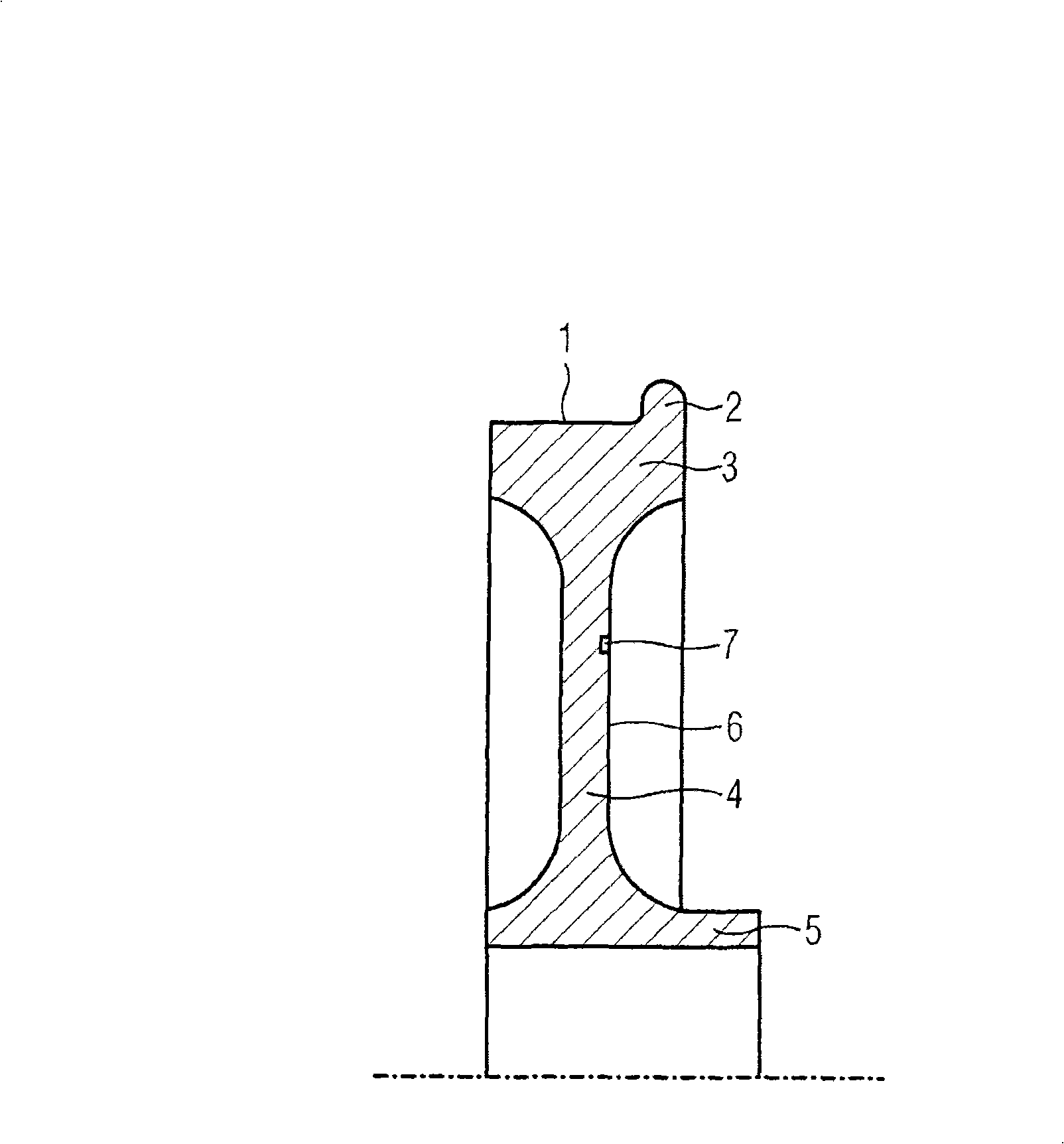
[0019] The railway wheel has a running surface 1 which is in contact with the rail, and in the region of this running surface 1 there is a flange 2 which holds the wheel on the rail. The running surface 1 and the flange 2 are components of the rim 3 . A spoke 4 is connected to the direction of the center of the wheel. The hub 5 is located in the region of the shaft. The surface area 6 acting as a friction ring is located on the spoke 4 . This surface area 6 has a special surface treatment. Grooves serving as wear markings 7 are provided on this surface region 6 .

[0020] For braking, a brake body (not shown) is pressed axially against surface region 6 .

[0021] With the brake device shown, the same effect can be achieved without wheel brake discs.


PUM


Abstract

The invention relates to a device for braking a rail vehicle, comprising a braking element that can be forced against a wheel. The invention is characterized in that the wheel comprises a surface area (6) which is used as a friction ring and against which the braking element can be forced.

Description

technical field [0001] The invention relates to a device for braking railway rolling stock, with braking bodies compressible onto wheels. Background technique [0002] Railway rolling stock has friction brakes, among other different braking systems, in which a brake body is pressed against a wheel or a component that turns with the wheel. In known shoe brakes, a brake shoe presses against the running surface of the rail wheel, whereby the running surface is subjected to mechanical loading and leads to heat input into the wheel via the running surface, which shortens the life of the wheel. And because the braking process may make the running surface rough, or even form grooves, further increasing the running noise, which is undesirable. [0003] It has been proposed to install disc brakes on railway rolling stock. A stationary brake body presses against a brake disc that rotates with the wheel. [0004] Eventually also small wheels have been proposed, with non-rotating bra...

Claims


Application Information

Patent Timeline
Patent Type & Authority Applications(China)
IPC IPC(8): B60B17/00
CPCF16D2065/1336F16D65/12F16D2065/1332F16D2069/004B60B17/0068B60B17/0006
Inventor 弗朗兹-约瑟夫·韦伯鲁迪格·曾兹
Owner SIEMENS AG
Why Eureka
Try Eureka