Mechanical seal device

A mechanical sealing device and sealing surface technology, applied in the direction of engine sealing, mechanical equipment, engine components, etc., can solve the problems of loss of elasticity and reduced sealing ability, and achieve the effects of easy assembly, simplified structure, and prevention of leakage.

Inactive Publication Date: 2008-11-26
EAGLE INDS
View PDF3 Cites 7 Cited by
  • Summary
  • Abstract
  • Description
  • Claims
  • Application Information

AI Technical Summary

Problems solved by technology

Since the two sealing surfaces 106, 111 will slide and generate heat while the vibration phenomenon occurs, the second O-ring 132 and the third O-ring 137 will be heated due to sliding heat, thus losing their elastic force, resulting in a decrease in sealing ability

Method used


Image

  • Mechanical seal device
  • Mechanical seal device
  • Mechanical seal device

Examples


Embodiment Construction

[0086] The mechanical seal device of the preferred embodiment of the present invention will be described in detail below with reference to the accompanying drawings. Each drawing described below is an accurate drawing based on design.

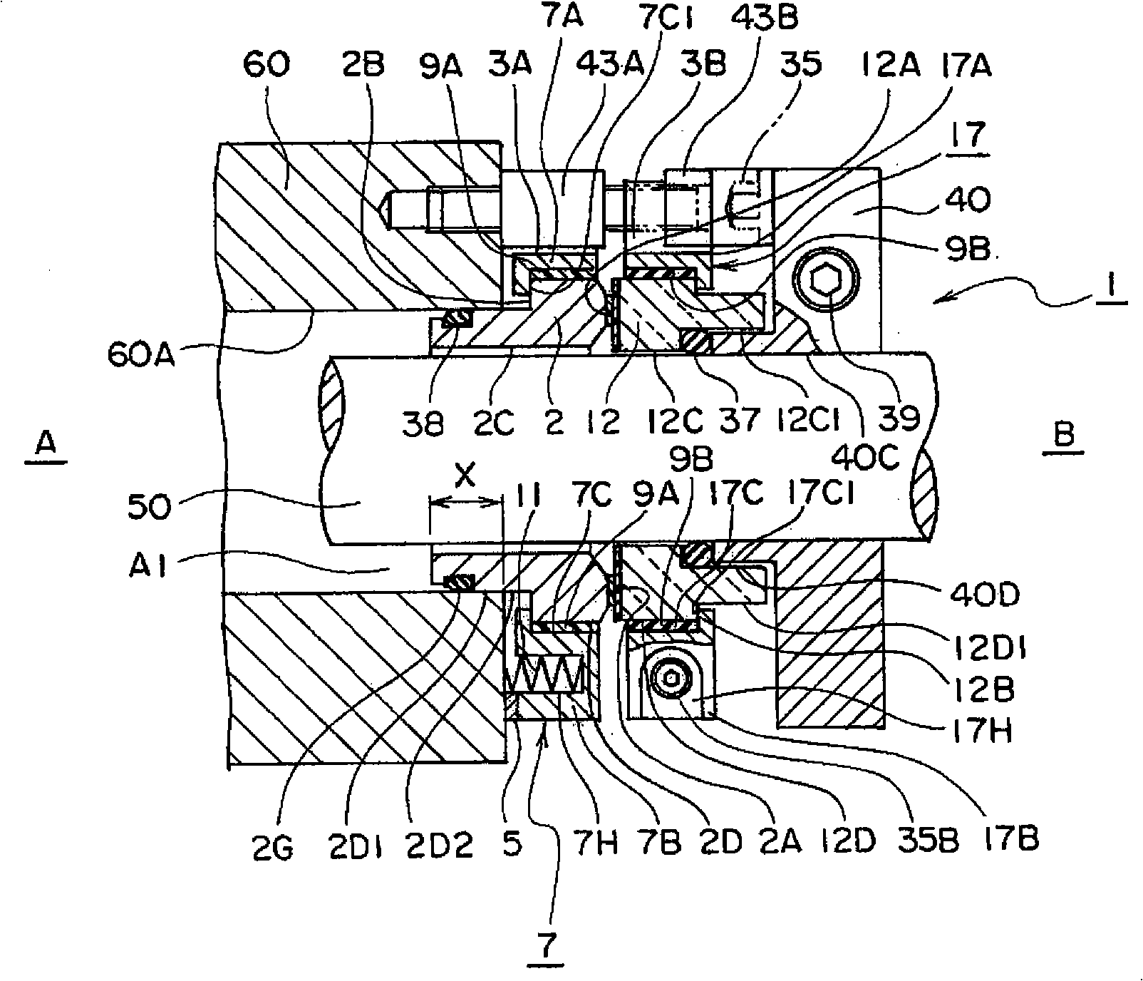
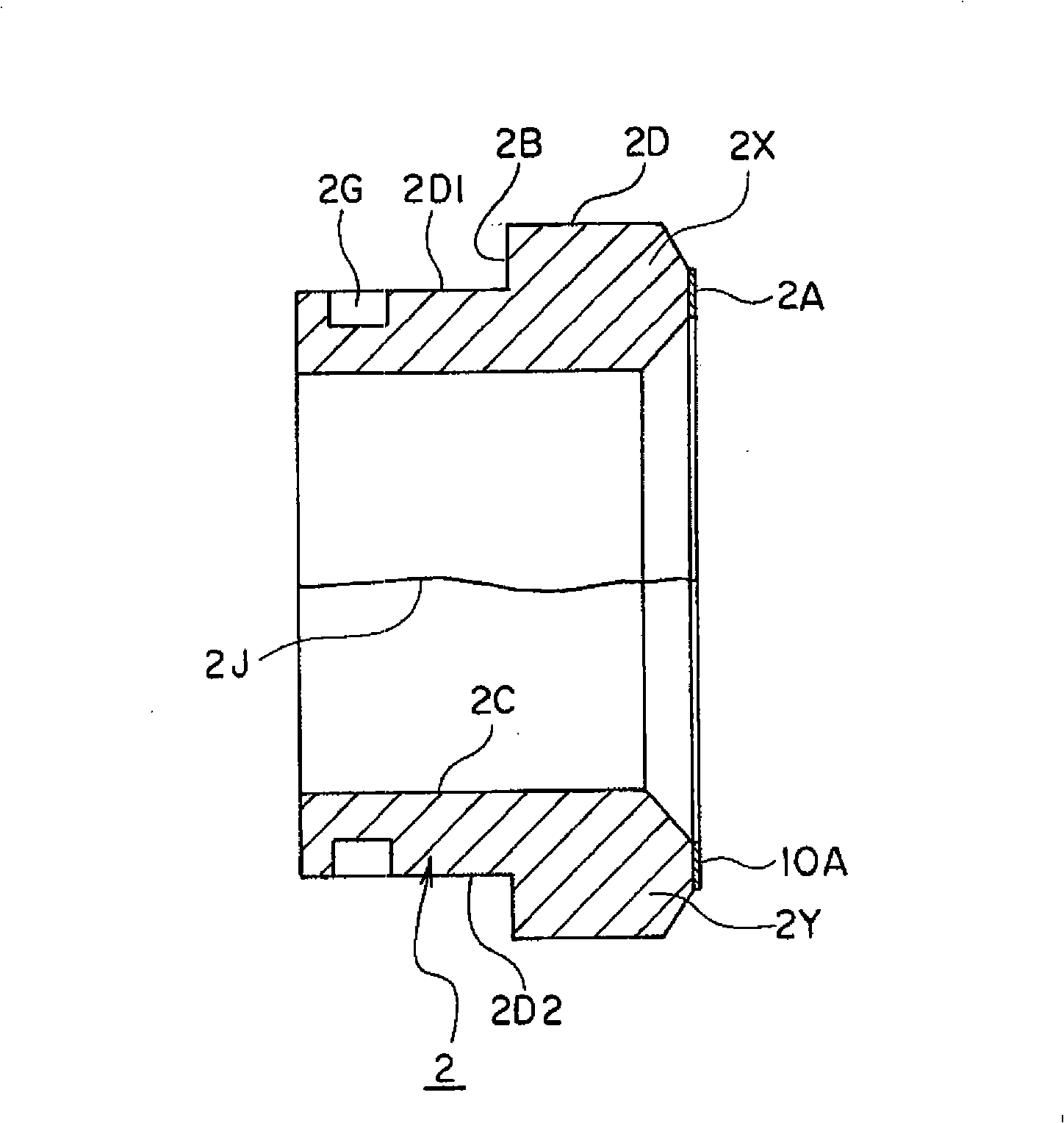
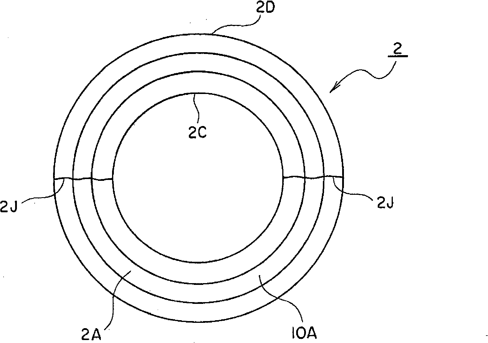
[0087] figure 1 It is a sectional view of the mechanical seal device 1 according to the first embodiment of the present invention. Figure 2A with Figure 2B yes figure 1 The split stationary seal ring 2, Figure 3A with Figure 3B yes figure 1 The split rotary seal ring 12. Refer below figure 1 , Figure 2A , Figure 2B , Figure 3A with Figure 3B Be explained. Symbol 1 is a mechanical seal device. The mechanical seal device 1 is installed on the side surface (outer surface) of the machine outer B of the casing 60 in order to seal the flow path A1, and the sealed fluid flows between the hole peripheral surface 60A of the casing 60 and the rotating shaft 50. flow within road A1. The flow path A1 in the casing 60 communicates...


PUM


Abstract

A mechanical seal device which is reduced in friction when seal surfaces slide on each other, prevented from abrasion on seal surfaces, is prevented from abnormal abrasion on the seal surface of a sealing ring and joining split surfaces, is prevented from seizure or squeal phenomena on seal surfaces when seal surfaces are abrasion-rotated and kept in a dry-friction state, is simplified in structure thereof, and is easier to assemble and disassemble. The mechanical seal device is a split type mechanical seal device that seals fluid to be sealed by being mounted to a surface outside a machine between a hole in a housing and a rotary shaft inserted into the hole, and comprises a split stationary sealing ring mounted and fixed to the rotary shaft by embracing it from the opposite sides, and a split rotating sealing ring fixed to the rotary shaft by embracing it from the opposite sides, wherein a clearance through which to permit fluid to be sealed to flow is provided between the inner peripheral surface of the split stationary sealing ring and the rotary shaft, and a rubber or resin sealing layer is provided on at least one of the seal surface of the split stationary sealing ring and the opposing seal surface of the split rotating sealing ring.

Description

technical field [0001] The present invention relates to a split-type mechanical seal device in which a seal ring split into two in the axial direction is assembled on the outer peripheral surface of a rotating shaft mounted on a machine in such a manner that the two split surfaces are joined to each other from both sides. It relates to a mechanical seal device in which the sealing performance of the split seal ring is improved. Background technique [0002] In the related technology of the present invention, there is a Image 6 The illustrated mechanical seal device 100 (see, for example, Patent Document 1, Patent Document 2, and Patent Document 3 below). Should Image 6 It is a side sectional view of the mechanical seal device 100 . The mechanical seal device 100 is a built-in seal. exist Image 6 Among them, the rotating shaft 148 passes through the passage 151 of the housing 150 . The end surface of the gland assembly 140 divided into two is joined to the end surface o...

Claims


Application Information

Patent Timeline
Patent Type & Authority Applications(China)
IPC IPC(8): F16J15/34
CPCF16J15/3488
Inventor 高桥秀和
Owner EAGLE INDS
Why Eureka
Try Eureka