Aircraft fuel pipe coupling

A technology for couplings and fuel pipes, applied in the direction of pipe joints, couplings, pipes/pipe joints/fittings, etc., to reduce manufacturing costs and the risk of assembly errors, and improve overall flexibility

Inactive Publication Date: 2008-11-26
AIRBUS OPERATIONS LTD
View PDF1 Cites 7 Cited by
  • Summary
  • Abstract
  • Description
  • Claims
  • Application Information

AI Technical Summary

Problems solved by technology

Prior art couplings also require complex electrical connections between the tubes

Method used


Image

  • Aircraft fuel pipe coupling
  • Aircraft fuel pipe coupling
  • Aircraft fuel pipe coupling

Examples


Embodiment Construction

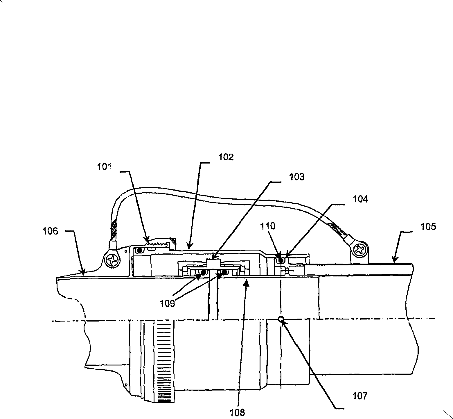
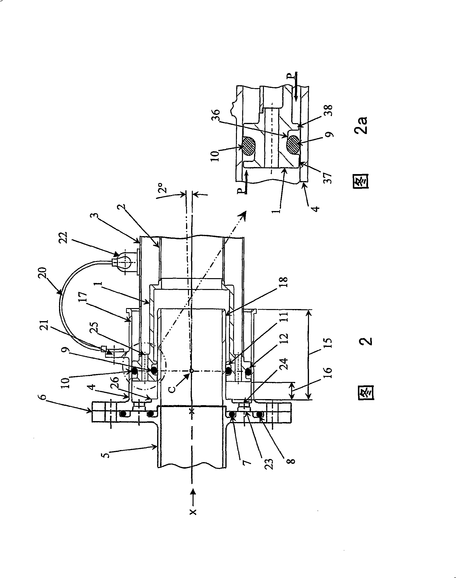
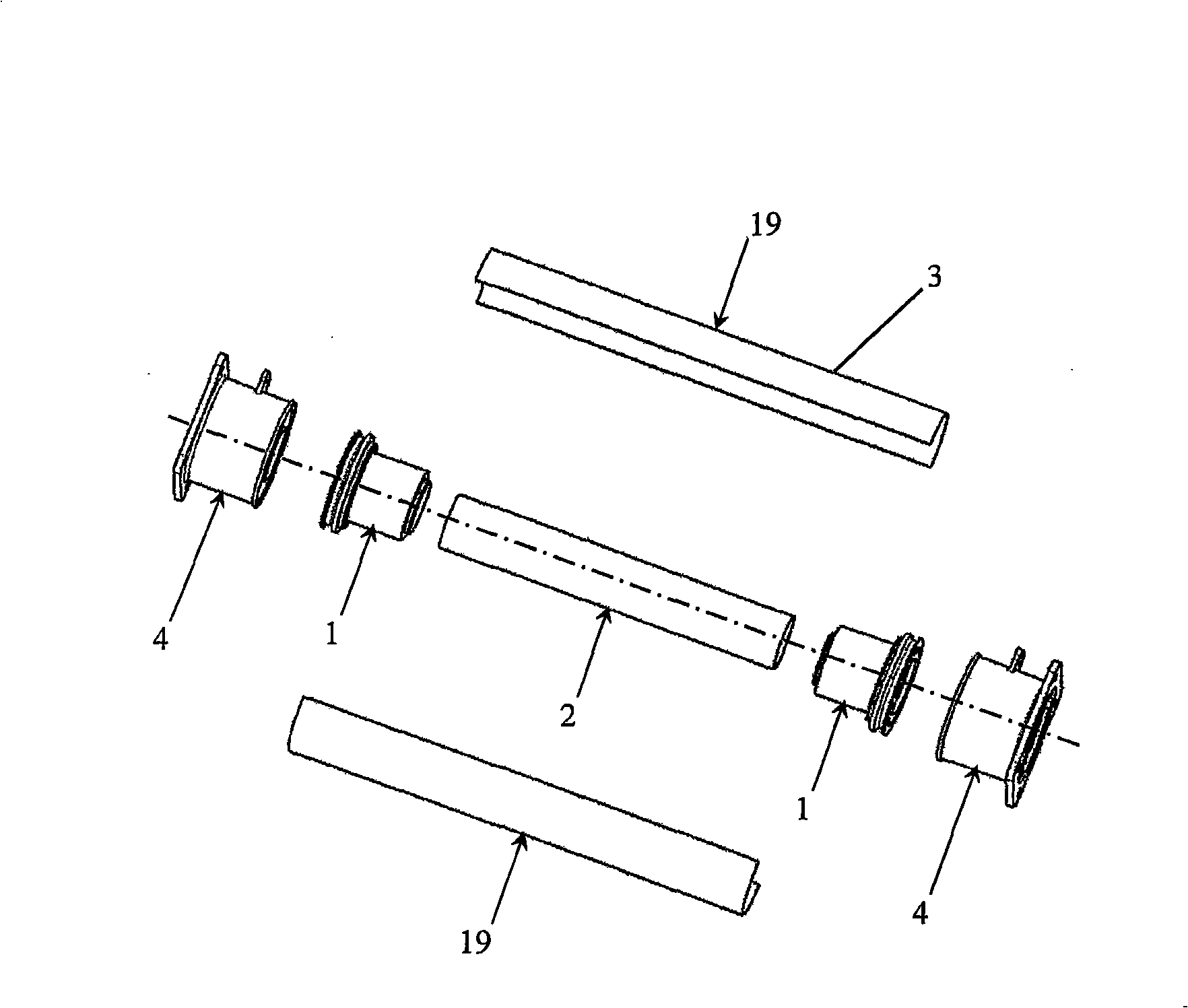
[0039] Figures 2 and 2a show a coupling according to a first embodiment of the invention. The coupling is arranged around the axis X and combines a single-walled rigid pipe 5 (left in FIG. 2 ) with a double-walled rigid pipe (right in FIG. 2 ) comprising an inner rigid pipe wall 2 and an outer rigid pipe wall 3 . The coupling comprises a single piece end fitting 1 attached to a double walled pipe 2, 3 by fusion welding. The coupler also includes a single-piece double-wall socket 4 attached to an adjacent single-wall tube 5 by a split flange comprising a flange on the single-tube wall 5 and a corresponding flange on the double-wall socket 4. The flange, the bisected line is indicated by arrow 6. The single wall tube 5 in this embodiment is in the form of a single wall connecting tube comprising end flanges which are rigidly attached to the aircraft structure (rear spar - not shown). The connection of the double wall socket 4 and the single wall tube 5 is sealed by an inner st...


PUM


Abstract

A coupling for connecting double-walled fuel comprises a pipe end fitting (1), which includes a male outer surface for example including a groove (12) and a female inner surface for example including a groove (11). The coupling also includes a double-walled socket (4), which includes a female outer socket (17) and a male inner shaft (18). The pipe end fitting is partially accommodated in the region between the female outer socket and the male inner shaft of the double-walled socket. A first seal ring (9) seals between the female inner surface of the pipe end fitting (1) and the male inner shaft (18) of the double-walled socket (4). A second seal ring (10) which may be substantially coplanar with the first, seals between the male outer surface of the pipe end fitting (1) and the female outer socket (17) of the double-walled socket (4).

Description

technical field [0001] The present invention relates to aircraft fuel line couplings, and in particular, but not exclusively, to flexible pipe couplings for connecting a double wall tube to another fuel line in an aircraft fuel system. Background technique [0002] In aircraft fuel systems, it is often necessary to use double wall pipes, fittings and couplings to protect fuel from leakage. When the risk of leakage is high, such as in the pressurized fuselage of an aircraft, the entire fuel system can be double-walled. Where there is less risk of leakage, only double wall couplings may be used. Additional complications arise due to the need to use flexible couplings to compensate for manufacturing tolerances, structural deviations and thermal effects. [0003] Figure 1 of the accompanying drawings shows a prior art connection of a single wall pipe (not shown, but positioned to the left of the coupling as shown in Figure 1 ) and a double wall pipe 102 (to the right of the co...

Claims


Application Information

Patent Timeline
Patent Type & Authority Applications(China)
IPC IPC(8): F16L39/00F16L39/04
CPCF16L2201/30F16L25/01F16L39/005F16L39/04B64D37/14
Inventor D·佩迪特A·J·布莱恩特
Owner AIRBUS OPERATIONS LTD
Why Eureka
Try Eureka