Helical material transport machine

A conveyor and material technology, applied in the direction of transportation and packaging, loading/unloading, containers, etc., can solve the problems of equipment continuous feeding, increased warehouse pressure, material arching, etc., to achieve smooth material transportation, avoid arching, The effect of low drag

Inactive Publication Date: 2008-12-03
钱尧翎
View PDF0 Cites 4 Cited by
  • Summary
  • Abstract
  • Description
  • Claims
  • Application Information

AI Technical Summary

Problems solved by technology

[0002] During the feeding process of the biomass feeding system of a biomass power plant, the material is fed through the rotation of the screw shaft in the multi-head screw feeding unit. Because of the characteristics and the warehouse pressure, there will be arching of the material and the increase of the warehouse pressure, which will have a great impact on the continuous feeding of the equipment, and the warehouse pressure is too large, which requires a high-power reducer and high energy consumption.

Method used


Image

  • Helical material transport machine
  • Helical material transport machine
  • Helical material transport machine

Examples


Embodiment Construction

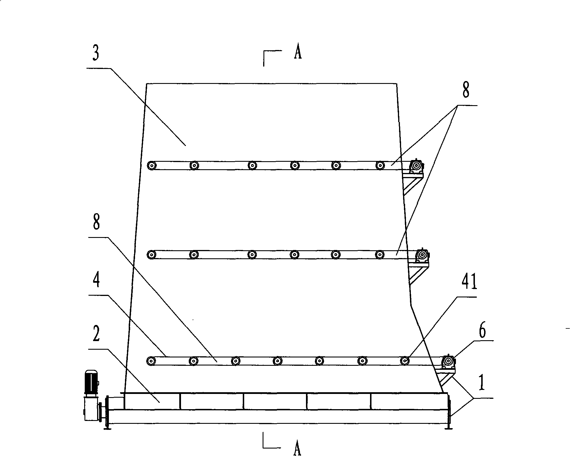
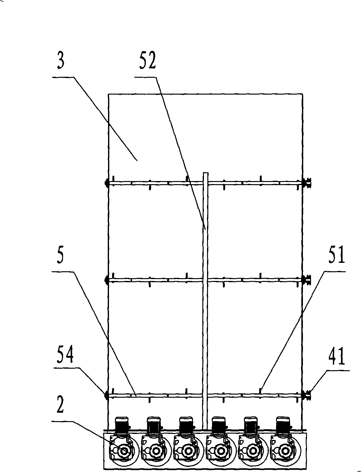
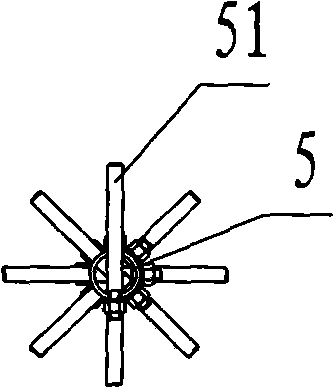
[0021] Such as figure 1 and figure 2 , is a kind of spiral material conveyor with loosening device of the present invention, comprises the screw material conveying unit 2 that is located on the frame 1, and the top of the screw material conveying unit 2 is provided with a silo 3, between the silo and the screw conveying unit 2 The junction is provided with a loosening device 8, and the middle and upper parts of the silo are also provided with a loosening device 8. The loosening device 8 includes a stirring shaft assembly flexibly installed on the feed bin 3, and the stirring shaft assembly includes a chain 4 linked A number of stirring shafts 5 and the motors 6 that are arranged on the frame 1 to drive the stirring shaft 5 to rotate, 54 in the figure are bearing seats, 41 are transmission sprockets, and the stirring shafts 5 pass through the bearing seats 54 arranged on the wall of the silo. It is flexibly installed at the junction of the silo and the screw conveyor unit 2. ...


PUM


Abstract

The invention discloses a helical material conveyer, comprising a helical material conveying unit arranged on a frame, wherein, a storage hopper is arranged above the helical material conveying unit. A loosening device is arranged on the junction of the storage hopper and the helical material conveying unit, and comprises a plurality of horizontally arranged stirring shaft components which are movably arranged on the storage hopper and are driven by a motor to operate. The middle part and the upper part of the storage hopper are also provided with a loosening device respectively for progressively loosening layer upon layer, thereby enhancing the loosening effect of materials. The invention has the loosening device arranged on the junction of the storage hopper and the helical material conveying unit, can loosen the constrictive material under the stir of a stirring shaft of the loosening device, thereby preventing the arch camber phenomenon of the materials, ensuring smooth conveying of the materials, realizing the feeding with low hopper pressure and low resistance, and reducing the energy consumption.

Description

technical field [0001] The invention relates to a material conveying device, in particular to a screw material conveying machine. Background technique [0002] During the feeding process of the biomass feeding system of a biomass power plant, the material is fed through the rotation of the screw shaft in the multi-head screw feeding unit, but during the transportation process, when encountering biomass such as straw and straw, the biomass material Because of the characteristics and the warehouse pressure, there will be arching of the material and the increase of the warehouse pressure, which will have a great impact on the continuous feeding of the equipment, and the warehouse pressure is too large, which requires a high-power reducer and high energy consumption. Contents of the invention [0003] The technical problem to be solved by the present invention is to provide a screw material conveyor, so as to solve the phenomenon of material arching during the conveying proces...

Claims


Application Information

Patent Timeline
Patent Type & Authority Applications(China)
IPC IPC(8): B65G65/46B65G33/26B65D88/64
Inventor 钱尧翎
Owner 钱尧翎
Why Eureka
Try Eureka