
Cross sliding type sublance system

A lateral movement and lateral movement technology, applied in the direction of manufacturing converters, etc., can solve the problem that the rotating frame type sub-gun cannot be added, and achieve the effect of practical design, stable and reliable operation, and easy installation

Inactive Publication Date: 2008-12-03
BAOSTEEL ENG & TECH GRP
View PDF0 Cites 4 Cited by
  • Summary
  • Abstract
  • Description
  • Claims
  • Application Information

AI Technical Summary

Problems solved by technology

[0003] The task of the present invention is to provide a laterally moving sub-gun system, which solves the problem that the traditional rotating frame type sub-gun cannot be added due to the limitation of existing factory facilities and other production conditions.

Method used


Image

  • Cross sliding type sublance system
  • Cross sliding type sublance system
  • Cross sliding type sublance system

Examples


Embodiment Construction

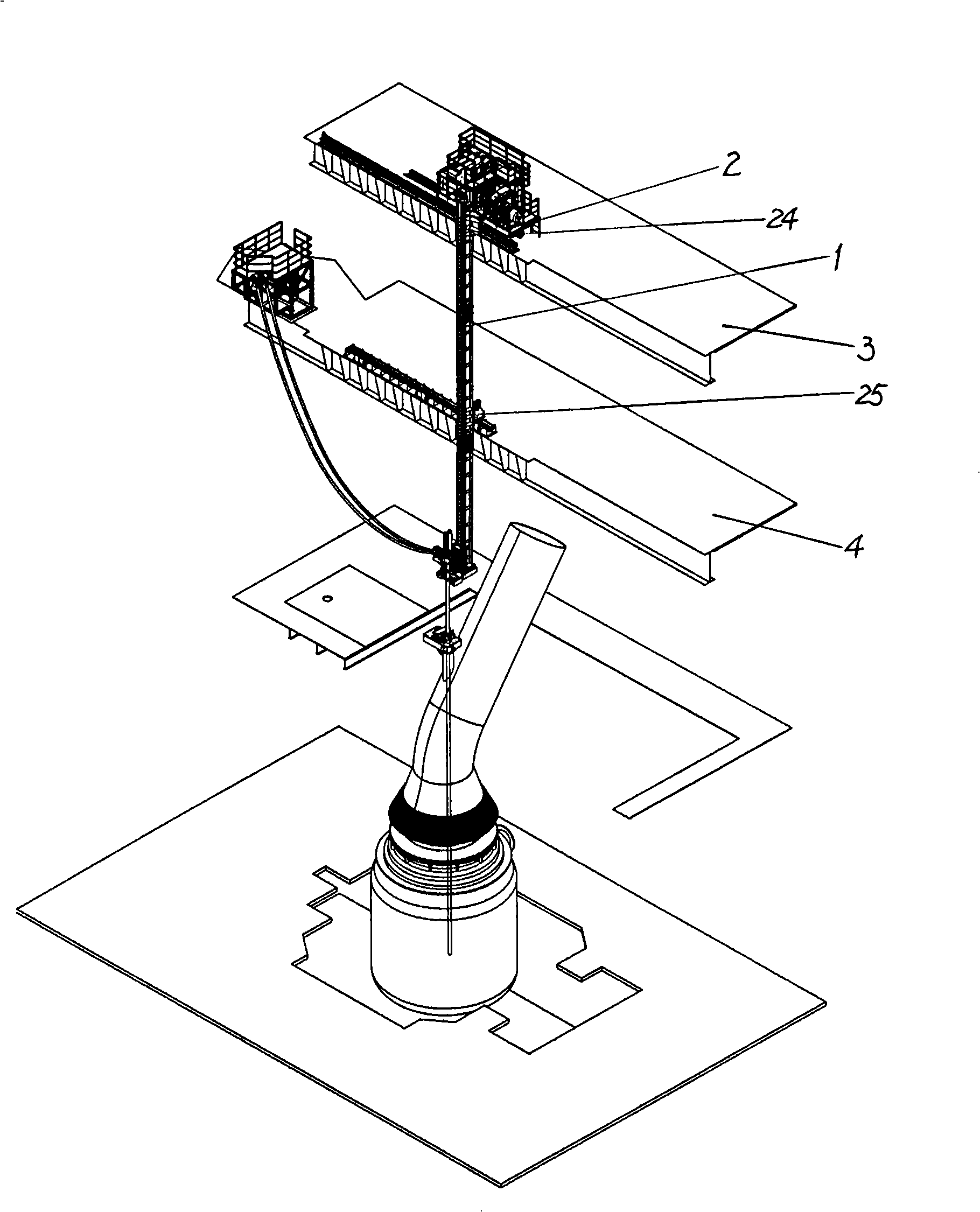
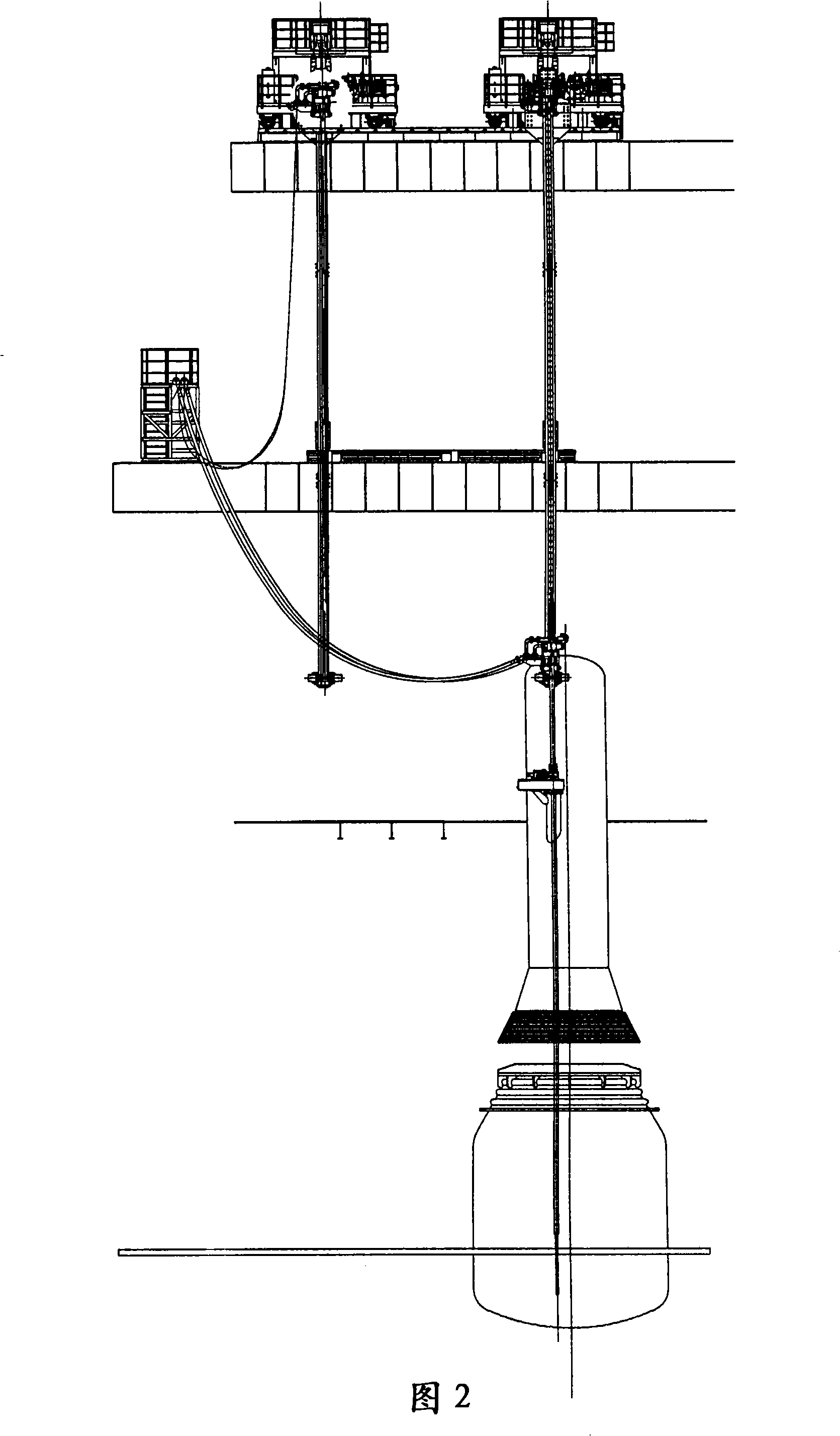
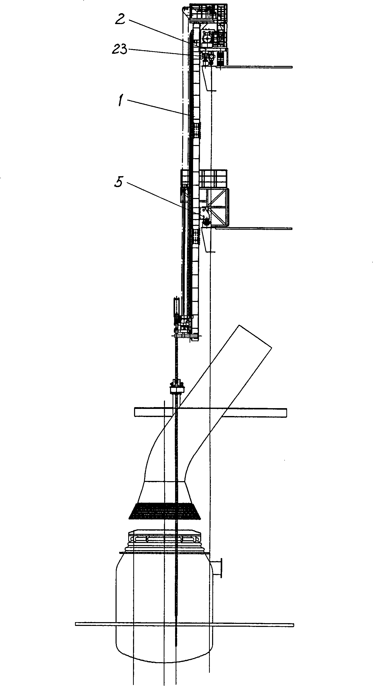
[0015] see Figure 1 to Figure 7 , a kind of traversing sub-gun system of the present invention comprises sub-gun system and frame, and frame is made up of lifting frame 1 and traversing frame 2.

[0016] The traversing frame 2 includes a traversing trolley frame body 21 , a traveling wheel set 22 , an upper side guide wheel device 23 , an upper track 24 , a lower track 25 and a lower side guide wheel device 26 . The traveling wheel group 22 is placed on the bottom of the traversing trolley frame body 21, and the upper track 24 is placed on the high-rise platform 3 perpendicular to the lifting frame 1, and the upper rail 24 supports the traveling wheel group 22 and the upper side guide wheel device 23.

[0017] Such as Figure 5 As shown in , the upper side guide wheel assembly 23 is laterally supported on the side of the upper rail 24 . The upper side guide wheel device 23 is provided with two guide wheels. The upper side guide wheel device 23 is provided with two guide wh...


PUM


Abstract

The invention relates to a cross sliding type sublance system, which comprises a sublance system and a frame. The frame comprises a lifting frame and a cross sliding frame; the cross sliding frame comprises a cross sliding trolley frame body, a running wheel group and an upper side guide wheel device which are arranged on the bottom of the cross sliding trolley frame body, an upper orbit which supports the running wheel group and the upper side guide wheel device, and a lower orbit and a lower side guide wheel device, wherein, the upper orbit is arranged on a high level platform which is perpendicular to the lifting frame, and the lower orbit is arranged on a low level platform which is perpendicular to the lifting frame; the lower side guide wheel device is arranged on the lifting frame through a bracket. The cross sliding type sublance system has the advantages that the design is practical, the manufacture is easy, the installation is convenient, the running is stable and reliable, the working cycle is short, etc. The cross sliding type sublance system is especially suitable for the reconstruction project for adding the sublance system in old steelworks.

Description

technical field [0001] The invention relates to steelmaking converter smelting equipment, relates to a sub-lance system used in supporting converter smelting in a steel-making workshop, and particularly relates to a laterally moving sub-lance system. Background technique [0002] With the improvement of the automation of converter smelting in domestic steelmaking plants and the increase in the requirements for steel varieties and specifications, most of the converters in newly built steel plants are equipped with sub-lance systems, and some steel plants that have been put into production are also considering adding sub-lances system. However, due to the limitations of the converter span of the existing plant, the overall height of the plant is low, the layout of peripheral equipment is complex, and production conditions, the commonly used rotary frame sub-lance cannot be used, so other structural types must be used. Designed to meet production needs. Contents of the inven...

Claims


Application Information

Patent Timeline
Patent Type & Authority Applications(China)
IPC IPC(8): C21C5/46
Inventor 章文超马立国隋立丽虞和祥
Owner BAOSTEEL ENG & TECH GRP
Learn More