High speed permanent magnet motor rotor

A technology for permanent magnet motors and rotors, which is applied in the direction of magnetic circuit rotating parts, magnetic circuit shape/style/structure, etc., and can solve the problems of irreversible high-temperature loss of magnetism, large eddy current loss, and temperature rise of solid rotors on the permanent magnet on the rotor side.

Active Publication Date: 2008-12-03
JING JIN ELECTRIC TECHNOLOGIES (BEIJING) CO LTD
View PDF0 Cites 12 Cited by
  • Summary
  • Abstract
  • Description
  • Claims
  • Application Information

AI Technical Summary

Problems solved by technology

[0004] In order to solve the problem that the existing high-speed permanent magnet motor has a large eddy current loss when a protective sleeve is added to the rotor side, the temperature rise of the sol

Method used


Image

  • High speed permanent magnet motor rotor
  • High speed permanent magnet motor rotor

Examples


specific Embodiment approach 1

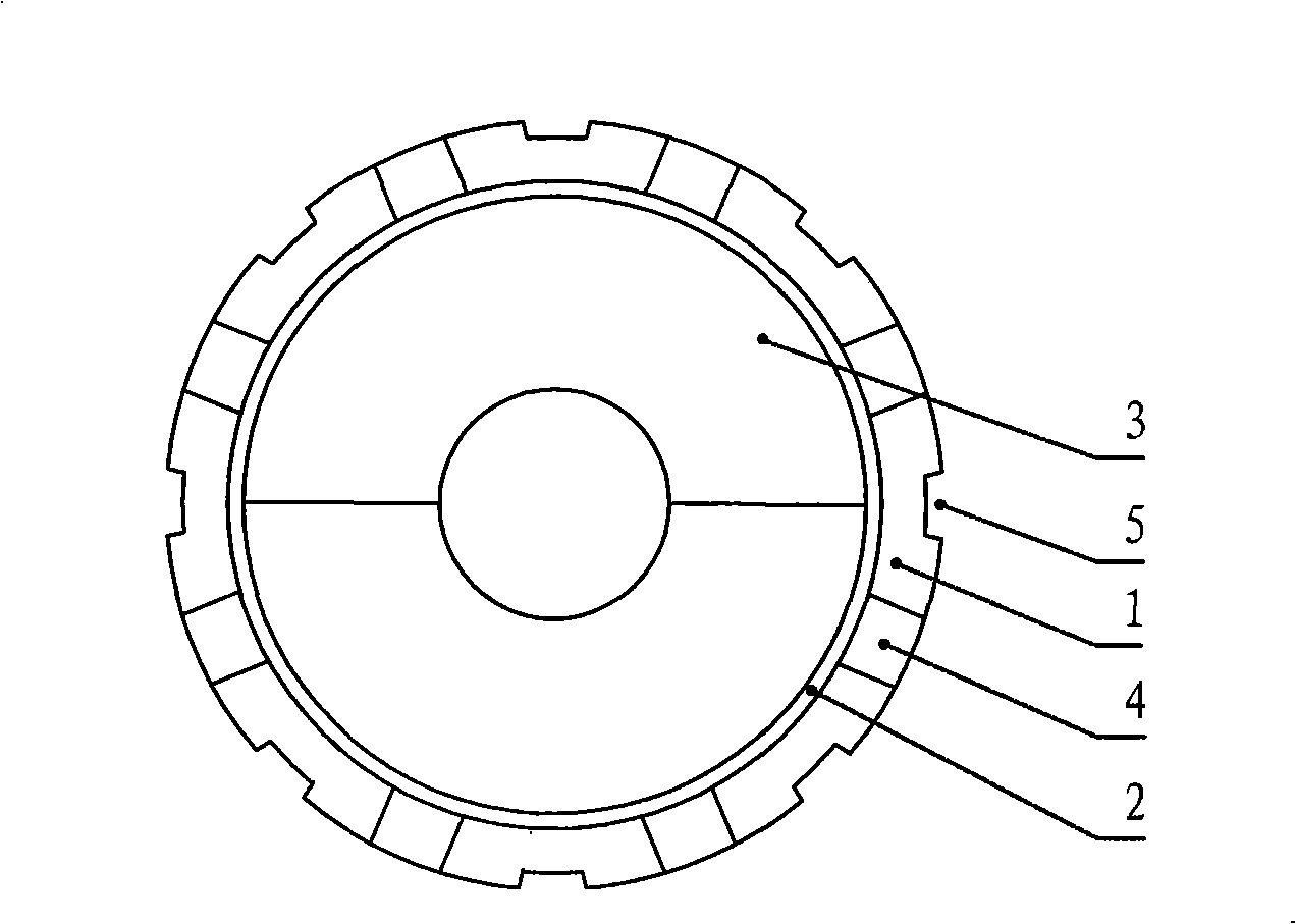
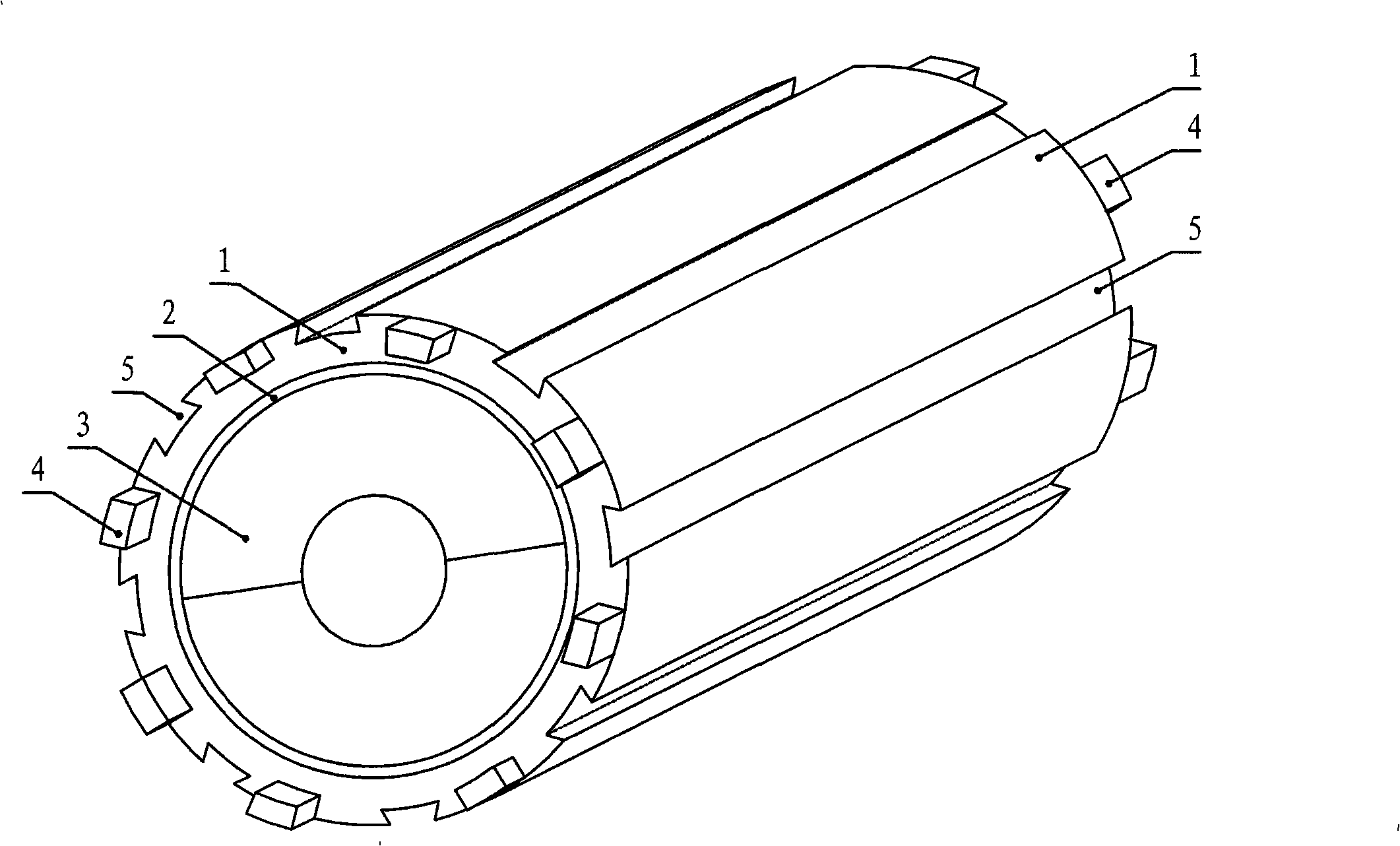
[0008] Embodiment 1: The rotor of a high-speed permanent magnet motor, which includes a rotor protection sleeve 1 , a permanent magnet 3 , and an insulating layer 2 located between the rotor protection sleeve 1 and the permanent magnet 3 .

specific Embodiment approach 2

[0009] Embodiment 2: The difference between this embodiment and the high-speed permanent magnet motor rotor described in Embodiment 1 is that a plurality of grooves 5 parallel to the central axis of the rotor are evenly distributed along the circumference of the outer surface of the rotor protection sleeve 1 .

[0010] The groove 5 in this embodiment can block the eddy current path of the rotor protection sleeve 1, reduce the eddy current and the resulting eddy current loss, and effectively reduce the heat generation on the rotor side, especially when the skin effect is obvious during startup. , the effect is more pronounced.

[0011] The cross-section of the groove 5 in this embodiment is an axisymmetric shape, and the extension line of the symmetric axis intersects the central axis of the rotor protection sleeve.

specific Embodiment approach 3

[0012] Specific embodiment three: The difference between this embodiment and the high-speed permanent magnet motor rotor described in specific embodiment one or two is that it also includes a plurality of protruding blocks 4, and the plurality of protruding blocks 4 are evenly distributed and fixed on the rotor protective sleeve on both ends of barrel 1.

[0013] The functions and effects of the raised block 4 added in this embodiment are as follows: 1. Since the raised block 4 is fixed on both ends of the rotor protection sleeve 1, it plays the role of the fan blade of the fan when the rotor rotates at high speed, which can enhance Axial airflow is formed in the air gap of the motor and in the groove 5, which enhances the cooling effect of the airflow. 2. The protruding blocks 4 are evenly distributed on the two end faces of the rotor protective sleeve, which plays a role in dynamic and static balance of the rotor body and reduces the occurrence of uneven magnetic tension.

...


PUM


Abstract

The invention relates to a high-speed permanent magnetic motor rotor, belonging to the field of motor. The high-speed permanent magnetic motor rotor solves the problems that the eddy current loss is comparatively large which leads to the temperature increment of the solid rotor to be excessively high easily and the permanent magnet beside the rotor to generate irreversible high-temperature loss of field when a protection sleeve is added beside the rotor in the existing high-speed permanent magnetic motor. The high-speed permanent magnetic motor rotor comprises a rotor protection sleeve (1), a permanent magnet (3), and an insulation layer (2) which is arranged between the rotor protection sleeve (1) and the permanent magnet (3). A plurality of concave troughs (5) which are parallel to the central axis line of the rotor are uniformly distributed on the rotor protection sleeve (1) along the circumference of the external surface of the rotor protection sleeve (1); two end surfaces of the rotor protection sleeve (1) are uniformly and fixedly provided with a plurality of bulges (4). The high-speed motor rotor of the invention is applicable to the existing high-speed permanent motors.

Description

technical field [0001] The invention relates to a high-speed permanent magnet motor rotor, which belongs to the field of motors. Background technique [0002] High-speed permanent magnet motors not only have the characteristics of high speed, high power density, high material utilization, fast dynamic response and high transmission system efficiency of ordinary high-speed motors, but also have the advantages of high efficiency and high power factor. Therefore, high-speed permanent magnet motors have good application prospects in centrifugal compressors of air conditioners or refrigerators, energy storage flywheels, textiles, high-speed grinders, hybrid vehicles, aviation, and ships. Especially in the distributed power generation system, the high-speed generator driven by the gas turbine is small in size and has high mobility. It can be used as a backup power source for hospitals, hotels and other important facilities, and can also be used as an independent power source or a ...

Claims


Application Information

Patent Timeline
IPC IPC(8): H02K1/27
Inventor 李伟力沈稼丰张晓晨霍菲阳谭天江
Owner JING JIN ELECTRIC TECHNOLOGIES (BEIJING) CO LTD
Why Eureka
Try Eureka