Liquid crystal panel and liquid crystal display device

A liquid crystal display device and liquid crystal panel technology, applied in optics, instruments, nonlinear optics, etc., can solve the problems of reducing chromatic aberration, suppressing uneven display, insufficient display, etc., achieving the goal of reducing chromatic aberration, superior picture contrast, and improving picture contrast Effect

Inactive Publication Date: 2008-12-03
NITTO DENKO CORP
View PDF11 Cites 4 Cited by
  • Summary
  • Abstract
  • Description
  • Claims
  • Application Information

AI Technical Summary

Problems solved by technology

However, these technologies are insufficient in improving screen contr

Method used


Image

  • Liquid crystal panel and liquid crystal display device
  • Liquid crystal panel and liquid crystal display device
  • Liquid crystal panel and liquid crystal display device

Examples


Example Embodiment

[0193] [Example 1]

[0194] (Formation of the first optical compensation layer)

[0195] A 110μm thick cellulose grease film [manufactured by Kaneka, trade name: KA, DSac (degree of acetyl substitution) = 0.04, DSpr (degree of substitution of propionyl) = 2.76], free-end stretched at 145°C to 1.5 The first optical compensation layer with a thickness of 108 μm was obtained. The photoelastic modulus of the obtained first optical compensation layer is 25×10 -12 (m 2 / N). The in-plane retardation of the obtained first optical compensation layer is Δnd(380)=102nm, Δnd(550)=140nm, Δnd(780)=163nm, and the thickness direction retardation is Rth(380)=105nm, Rth(550) =145nm, Rth(780)=169nm. The refractive index distribution at 550nm is

[0196] (Production of polarizing plate with first optical compensation layer)

[0197] After dyeing the polyvinyl alcohol film in an iodine-containing aqueous solution, the polyvinyl alcohol film is uniaxially stretched to 6 times in the boric acid-contain...


PUM

PropertyMeasurementUnit
Thicknessaaaaaaaaaa

Abstract

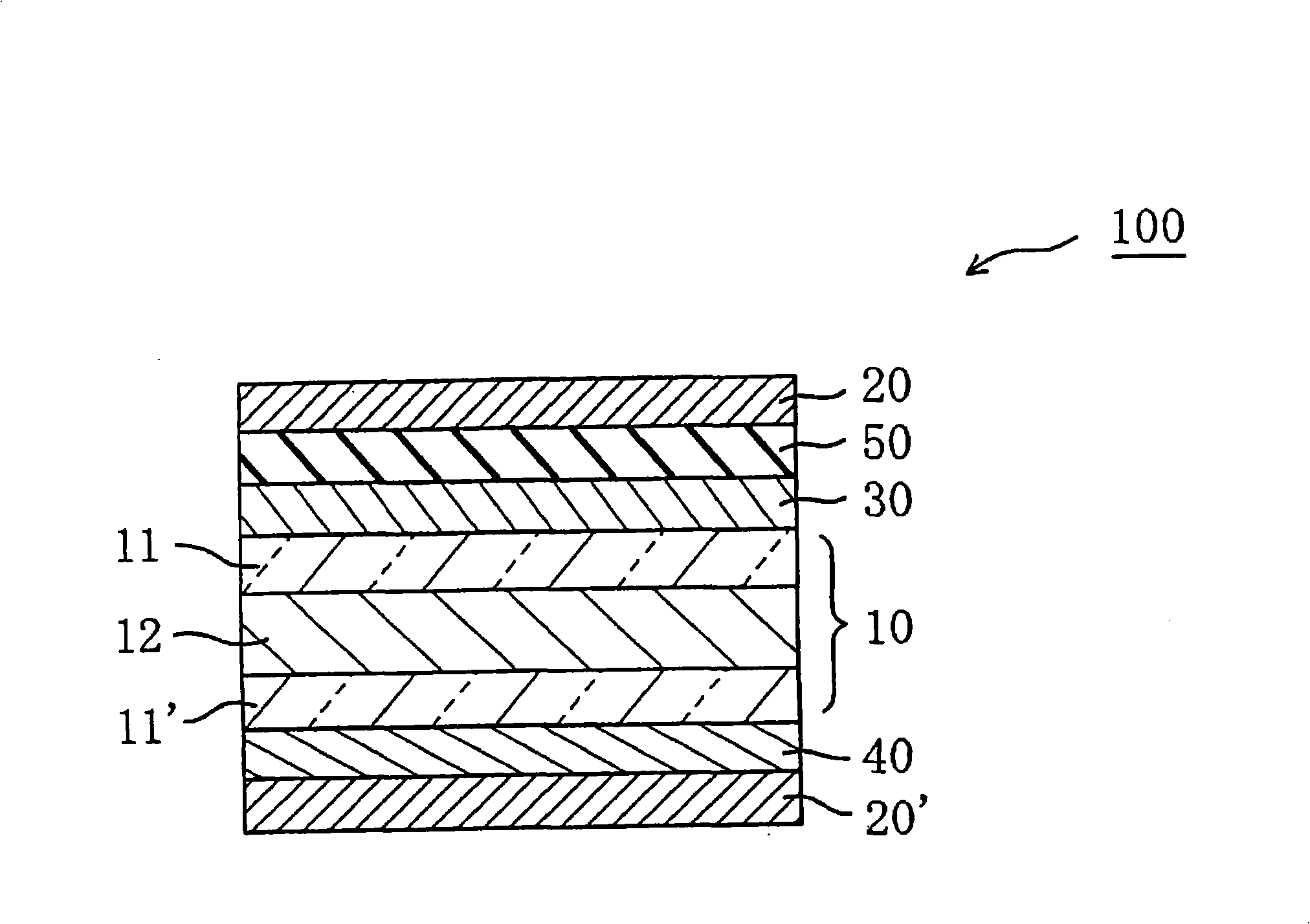
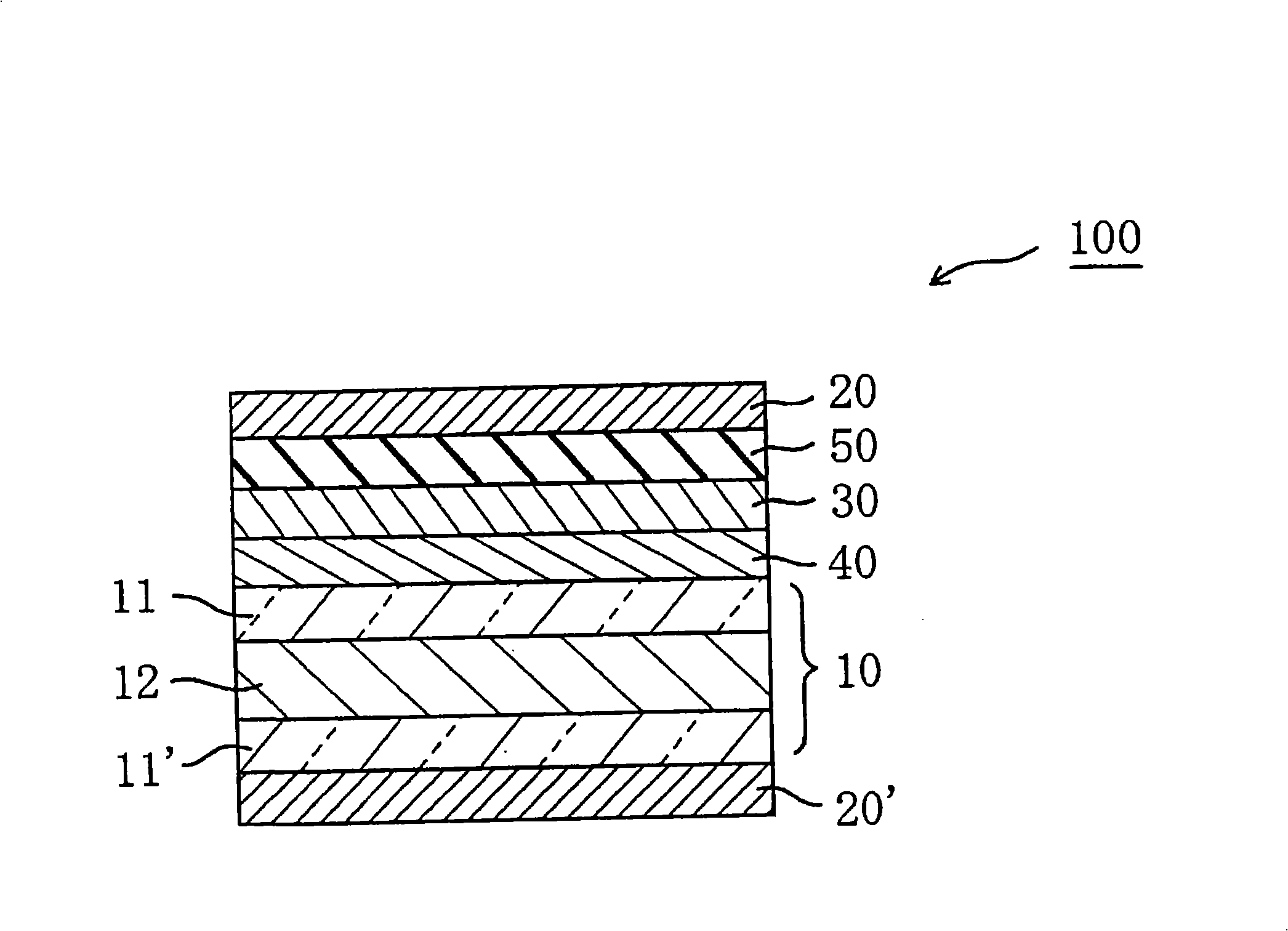
It is possible to provide a liquid crystal panel having an excellent screen contrast, a small color shift, and little display irregularities. The liquid crystal panel includes a liquid crystal cell, a first polarizer, a second polarizer, a protection layer, a first optical compensation layer, and a second optical compensation layer. A layer to be protected satisfies the relationships: 0 nm<=delta nd(550)<=10 nm and 0 nm<=Rth (550)<=20 nm. The first optical compensation layer has an absolute value of the optical elastic coefficient equal to or below 40*10<-12> (m<2>/N) and satisfies the relationships: delta nd(380) < delta nd(550) ny>=nz and 90 nm<=delta nd(550)<=200 nm. The second optical compensation layer satisfies the relationships: Rth (380)> Rth(550)>Rth (780) and nx=ny>nz.

Description

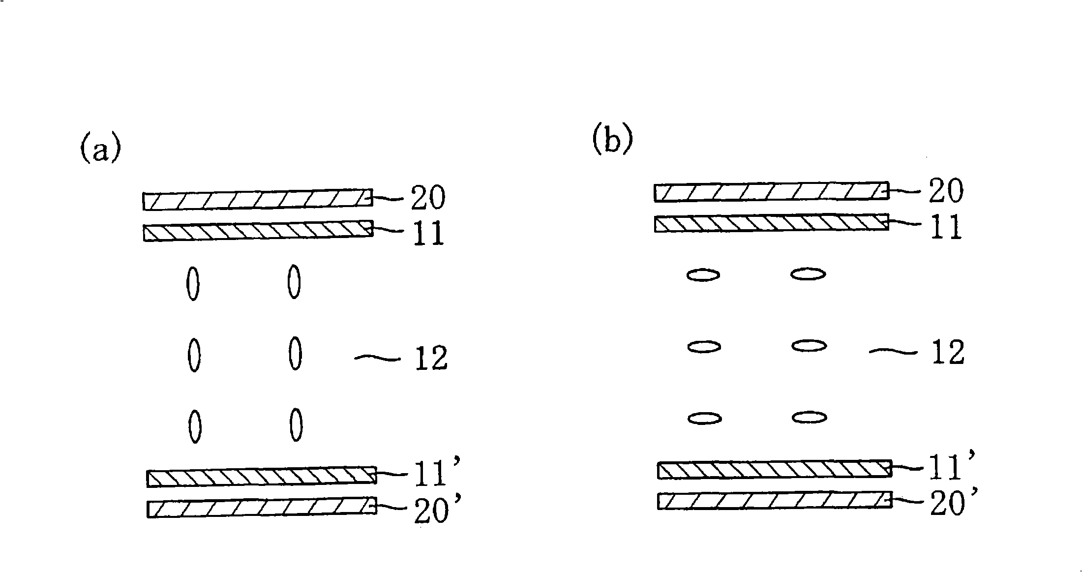
technical field [0001] The present invention relates to a liquid crystal panel and a liquid crystal display device, and more specifically, to a liquid crystal panel and a liquid crystal display device having at least two optical compensation layers between a first polarizing plate and a second polarizing plate. Background technique [0002] In a VA-mode or OCB-mode liquid crystal cell, liquid crystal molecules are aligned in a vertical direction when no voltage is applied. Therefore, when viewing the liquid crystal panel from an oblique direction, in appearance, the liquid crystal molecules are aligned in an oblique direction, and the polarization state of light from the oblique direction will be changed due to the birefringence of the liquid crystal, and the polarization from the polarization will be generated. Board light leaks. In addition, the polarizing plates are stacked and arranged so that their absorption axes are perpendicular to block light. When the polarizing p...

Claims


Application Information

Patent Timeline
IPC IPC(8): G02F1/13363G02B5/30G02F1/1335
Inventor 武田健太郎村上奈穗长濑纯一饭田敏行小林贯人
Owner NITTO DENKO CORP
Why Eureka
Try Eureka