

Concrete permeability measurement apparatus
A measuring device and permeability technology, which is applied in the direction of measuring device, permeability/surface area analysis, suspension and porous material analysis, etc., can solve the problem that the electric quantity method cannot solve the permeability evaluation of concrete with salt admixture, inaccurate measurement, Long test time and other problems, to achieve the effect of short test time, accurate measurement and simple structure
- Summary
- Abstract
- Description
- Claims
- Application Information
AI Technical Summary
Problems solved by technology
Method used
Image

Examples
specific Embodiment approach 1
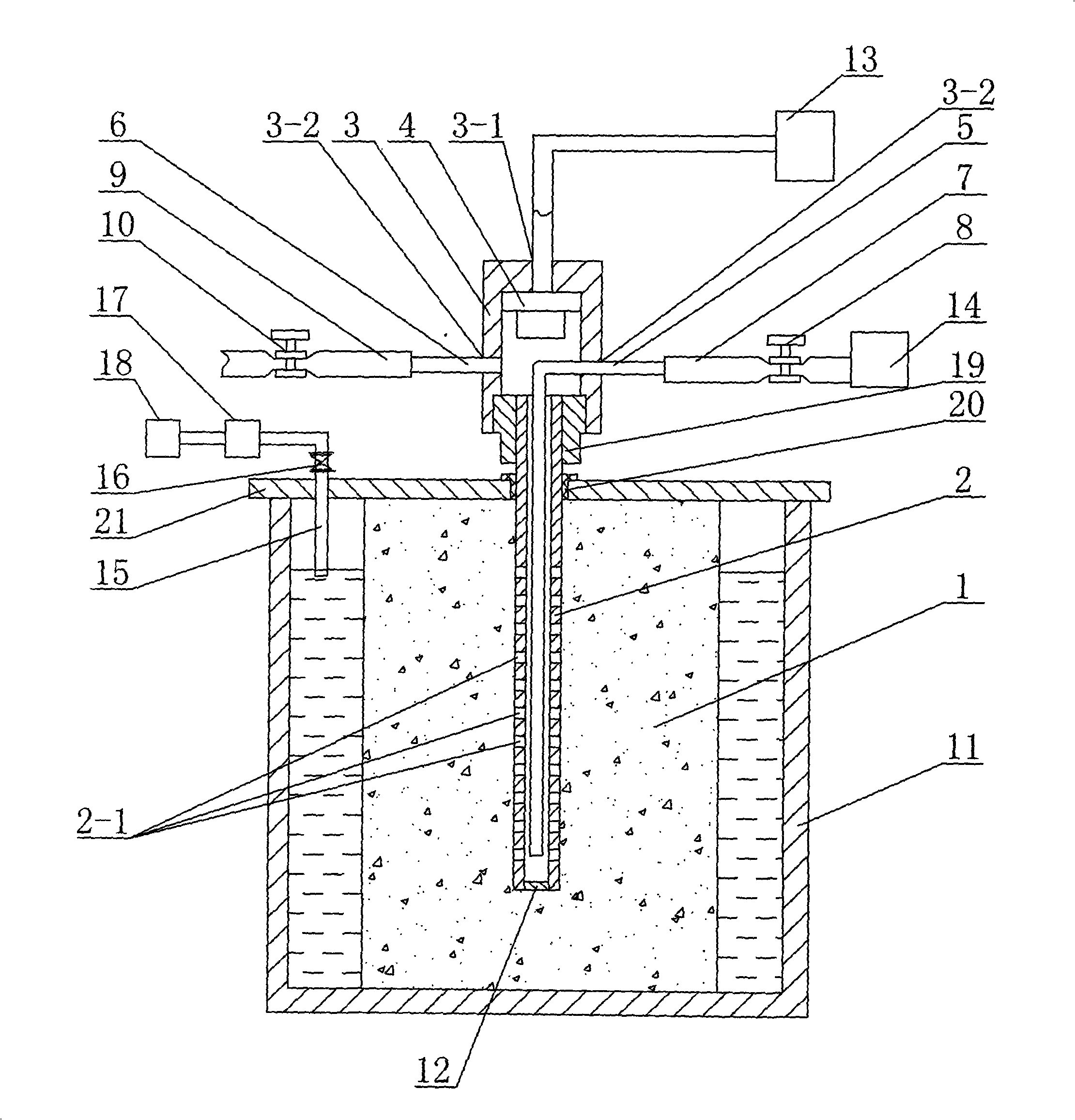
[0007] Specific implementation mode one: combine figure 1 Describe this embodiment, this embodiment includes concrete sample 1, first steel pipe 2, nut 3, humidity sensor 4, second steel pipe 5, third steel pipe 6, first soft rubber hose 7, first pipe clamp 8, the first Two soft rubber hoses 9, a second pipe clip 10, a container 11, a head 12, an external computer 13, a cover plate 21, a joint 19 and a nitrogen bottle 14, the cover plate 21 is installed on the upper end surface of the container 11, and the first The lower part of a steel pipe 2 is pre-buried in the center of the concrete sample 1, a plurality of penetration holes 2-1 are opened on the pipe wall of the lower part of the first steel pipe 2, and a sealing head 12 is fixedly installed on the lower end surface of the first steel pipe 2, so that The upper end of the first steel pipe 2 passes through the cover plate 21 and is installed in the joint 19, the outer wall of the joint 19 is threadedly connected with the n...
specific Embodiment approach 2
[0008] Specific implementation mode two: combination figure 1 To describe this embodiment, a plurality of permeation holes 2 - 1 in this embodiment are evenly opened on the pipe wall at the lower part of the first steel pipe 2 . So set, the penetration is uniform. Other compositions and connections are the same as in the first embodiment.
specific Embodiment approach 3
[0009] Specific implementation mode three: combination figure 1 Describe this embodiment, the difference between this embodiment and specific embodiment 1 is that it also adds a water pressure pipe 15, a valve 16, a pressure gauge 17 and a pressurizing device 18, and one end of the water pressure pipe 15 passes through the cover The plate 21 is inserted into the cavity formed between the container 11 and the concrete sample 1, the other end of the hydraulic pipe 15 is equipped with a pressurizing device 21, and the valve 16 is installed on the hydraulic pipe 15 at the end away from the pressurizing device 18 , the pressure gauge 17 is installed on the hydraulic pipe 15 between the pressurizing device 18 and the valve 16 . Such setting effectively shortens the test time. Other compositions and connections are the same as in the first embodiment.
PUM
 Abstract
Description
Claims
Application Information