Vision detection apparatus used for slender cavity

A technology of visual inspection device and slender cavity, which is applied to measurement devices, optical devices, instruments, etc., can solve the problems of difficulty in precise positioning of the end camera system, reduce costs, etc., and achieve the effect of low cost and high rigidity

Inactive Publication Date: 2008-12-10
HUAZHONG UNIV OF SCI & TECH
View PDF0 Cites 25 Cited by
  • Summary
  • Abstract
  • Description
  • Claims
  • Application Information

AI Technical Summary

Problems solved by technology

[0003] The invention provides a visual detection device for a slender cavity, which solves the problem

Method used


Image

  • Vision detection apparatus used for slender cavity
  • Vision detection apparatus used for slender cavity

Examples


Embodiment Construction

[0021] The present invention will be further described below in conjunction with drawings and embodiments.

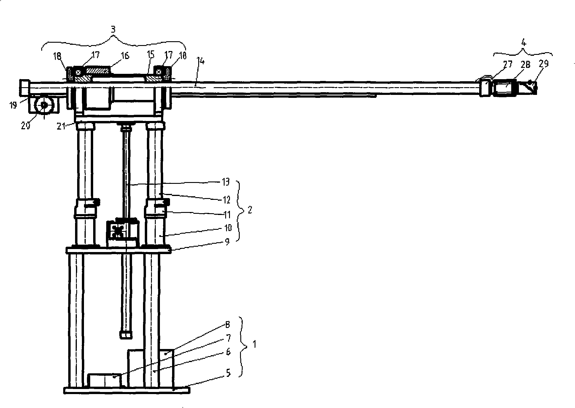
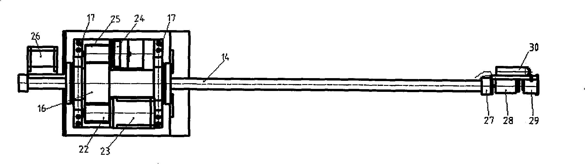
[0022] figure 1 , figure 2 The illustrated embodiment consists of a base 1 , a lifting mechanism 2 , a moving mechanism 3 and a camera system 4 .

[0023] Base 1 comprises base plate 5, support bar 6, control box 7 and motor driver 8; Support bar 6, control box 7, motor driver 8 are all fixed on the base plate 5; The bottom of base plate 5 can install roller so that whole mechanism can move.

[0024] The lifting mechanism 2 includes a lifting table 9, a guide rod cover 10, a brake cover 11, a guide rod 12 and an elevator 13; the vertical direction of the elevator is jointly determined by the guide rod cover 10 and the guide rod 12; the elevator 13 drives the motion mechanism 3 to move vertically ; The brake sleeve 11 is threadedly connected with the guide rod sleeve 10, and the brake sleeve 11 holds or loosens the support rod 6 so that the lifting mechanism 2 stops o...


PUM


Abstract

The invention relates to a visual detection device used for a fine long cavity body, belonging to the visual detection device. The problem that an end photographing system can not precisely position is solved and simultaneously the cost is lowered. The detection device comprises a base, a lifting mechanism, a motion mechanism and a photographing system. The vertically directional displacement of the motion mechanism is adjusted by the lifting mechanism to lead to the coaxial type of a probing rod and the cavity body to be detected. The motion mechanism comprises the probing rod, a probing rod hollow sleeve, a central gear, a probing rod supporting base, a translational motor cabinet, a rack, a translational motor gear, a motion supporting station, a rotary motor gear, a rotary motor and a translational motor. The photographing system is arranged on the probing bar end of the motion mechanism and comprises a supporting board, a photographer, a prism and a light source. Based on the design of a cylindrical coordinates, the device has the advantages of circumferential rotation, axis translation, radial fine adjustment, small gyration radius, long axial stroke, good rigidity and convenient processing and manufacturing. The visual detection device is applied to the assembling, the painting or the welding quality detection of fine long cylindrical cavity body which is not sealed or is provided with one sealed end and can not be reached by human.

Description

technical field [0001] The invention belongs to a visual detection device, in particular to a visual detection device for a slender cavity. Background technique [0002] The visual inspection device used for slender cavities is a component that provides internal assembly, spraying or welding quality for cavities with relatively large slenderness. Accurately read images in a small area. The processing requirements for the slender probe rods required for large-scale detection are very high. Usually, high-precision slider mechanisms or linear motors are used, which is very costly. Using existing cold-drawn profiles to develop large-stroke high-precision mechanisms can significantly reduce costs. The existing internal assembly, spraying or welding quality inspection mechanism of the slender cavity is usually endoscope type, its structure is flexible, and the terminal camera system is difficult to accurately locate. Contents of the invention [0003] The invention provides a ...

Claims


Application Information

Patent Timeline
IPC IPC(8): G01N21/954G01B11/00G02B23/24
Inventor 李世其刘洋彭涛马天阳徐迟王锐王峻峰
Owner HUAZHONG UNIV OF SCI & TECH
Why Eureka
Try Eureka