Full optical fiber current sensor

A current sensor and all-fiber technology, applied in voltage/current isolation, light guide, optics, etc., can solve problems such as no practical value, unstable Sagnac interference optical path, etc., to eliminate imperfection problems, stabilize Sagnac interference optical path, reduce noise effect

Inactive Publication Date: 2008-12-10
上海康阔光智能技术有限公司
View PDF1 Cites 33 Cited by
  • Summary
  • Abstract
  • Description
  • Claims
  • Application Information

AI Technical Summary

Problems solved by technology

[0006] In view of the above shortcomings of the current sensor composed of 2x2 fiber optic couplers, the industry tries to use 3x3 fiber optic couplers to form a Sagnac optical circuit to solve the problem of phase bias. The optical fiber has no ability to maintain polarization, so the Sagnac interference optical path composed of a 3x3 fiber coupler prepared by a conventional optical fiber is unstable and has no practical value

Method used


Image

  • Full optical fiber current sensor
  • Full optical fiber current sensor
  • Full optical fiber current sensor

Examples


Embodiment Construction

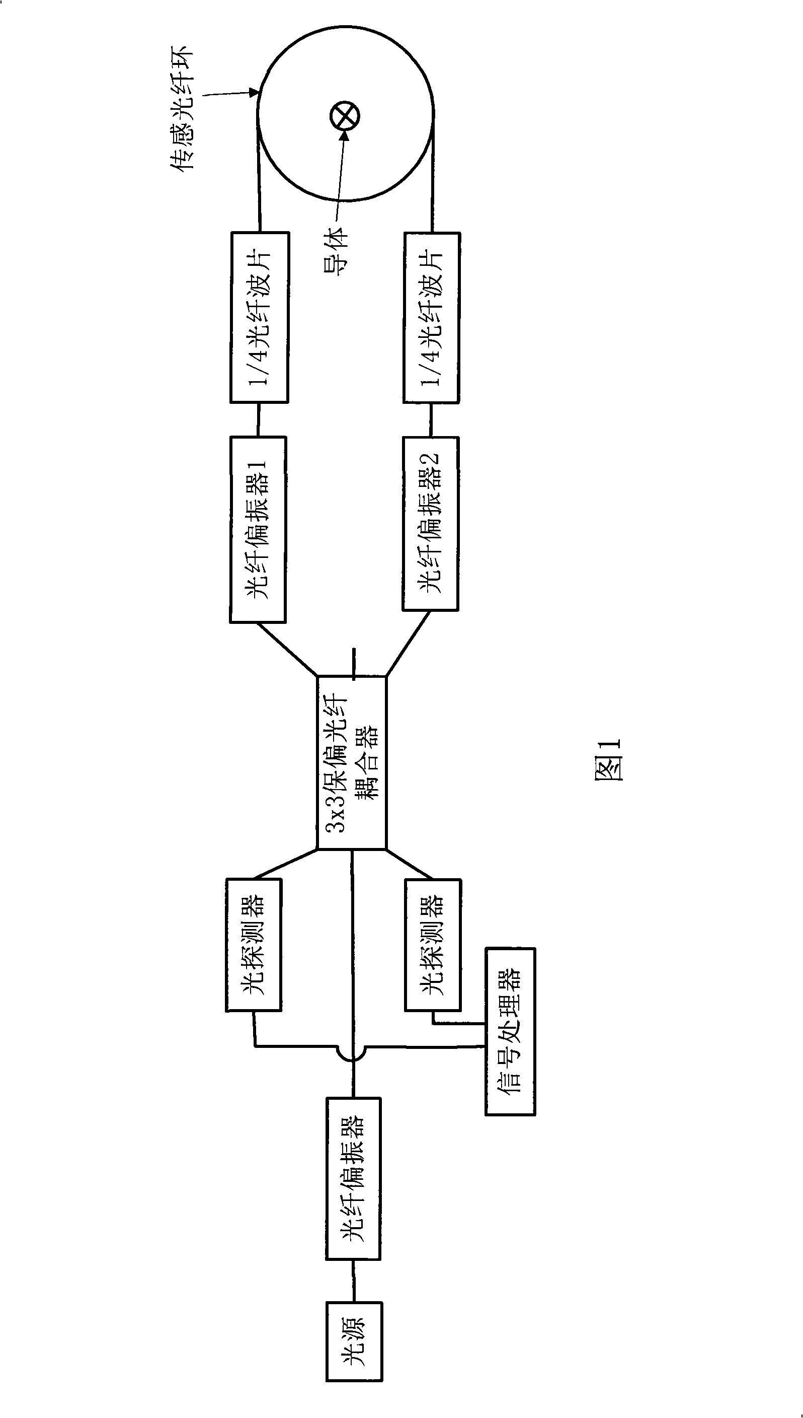
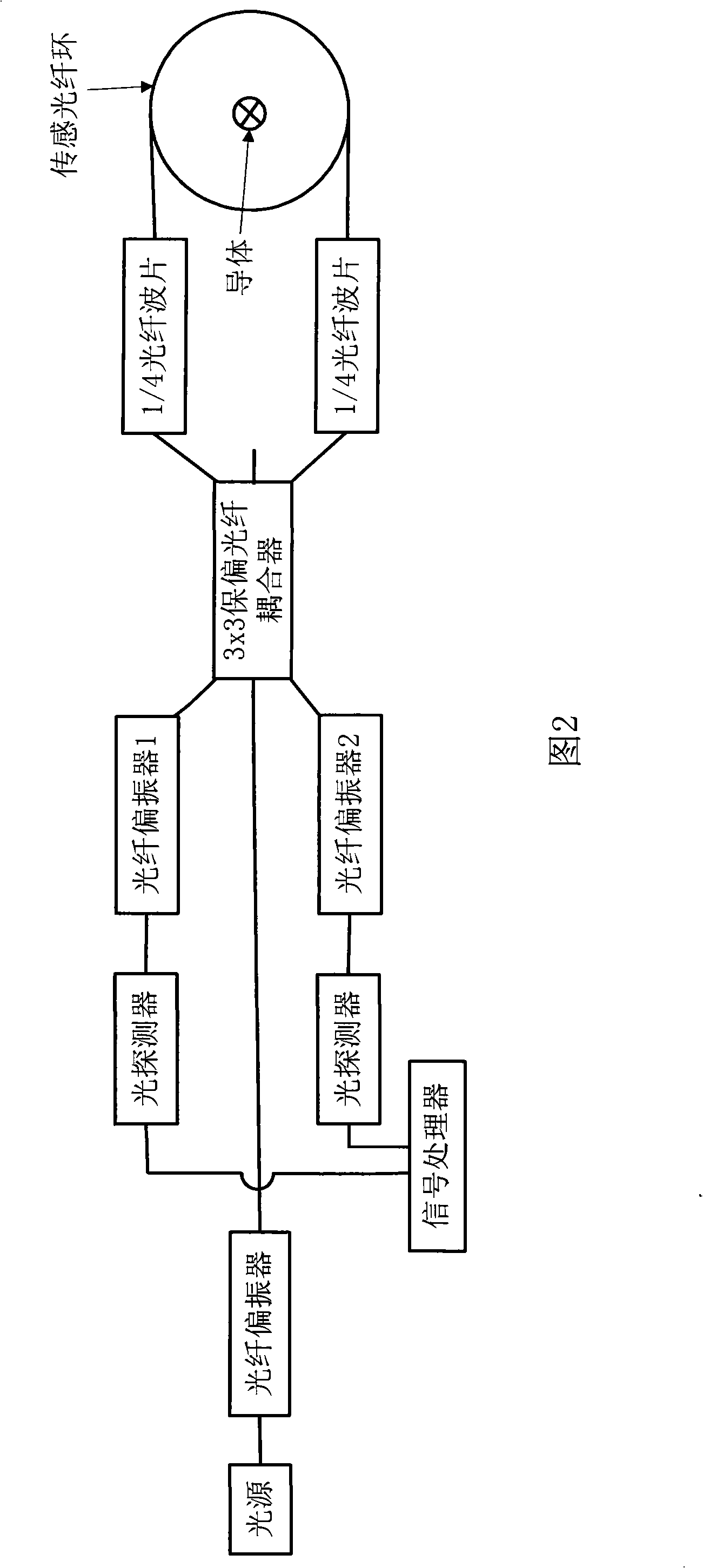
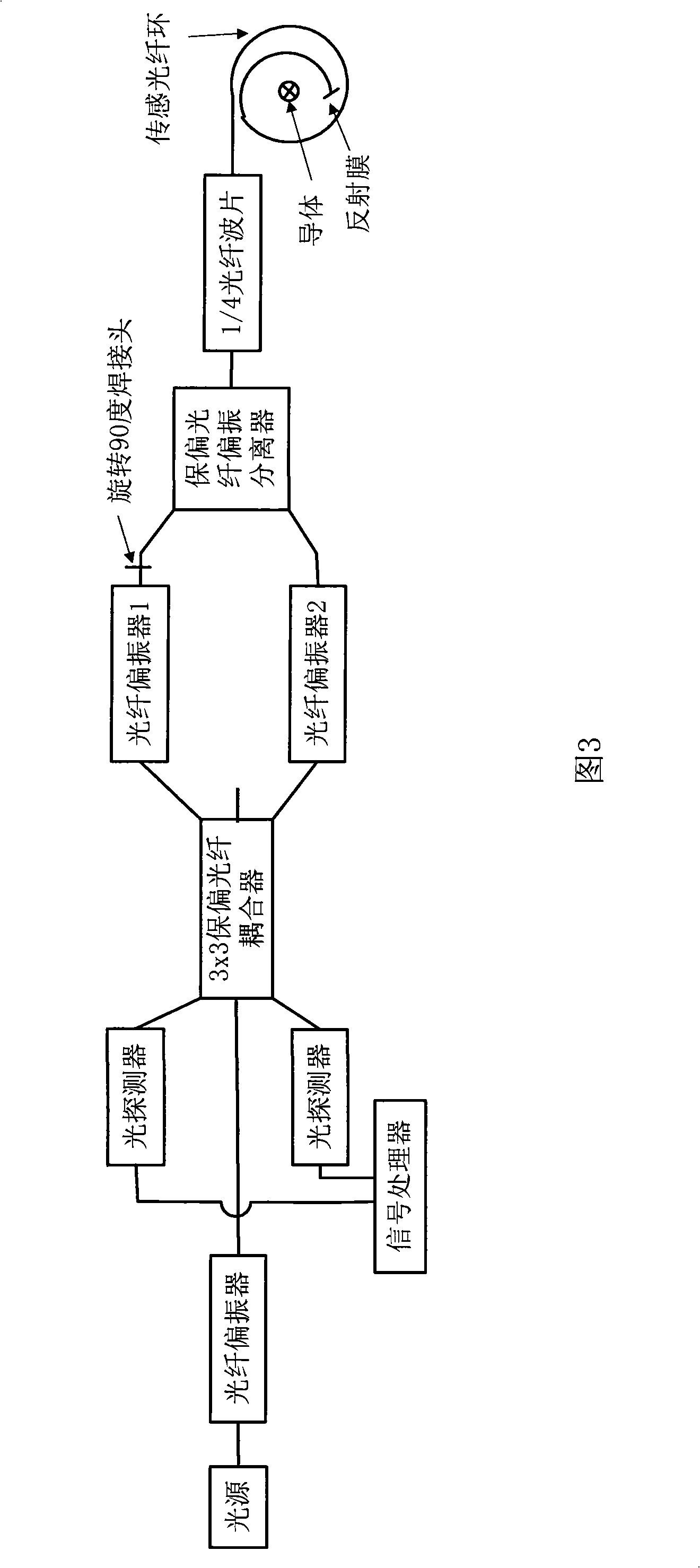
[0018] The optical coupler in the all-optical current sensor of the present invention adopts 3x3 polarization-maintaining optical fiber coupler, and the following introduction adopts two kinds of all-optical-optic current sensors of the present invention: the first kind of all-optical current sensor mainly consists of light source, 3x3 polarization-maintaining optical fiber coupler , fiber polarizer, 1 / 4 fiber wave plate, polarization-maintaining fiber polarization splitter (1x2 polarization-maintaining fiber coupler can also be used) and sensing fiber ring (surrounding the conductor), called reflective interference type all-fiber current Sensor; the second type of all-fiber-optic current sensor is mainly composed of a light source, 3x3 polarization-maintaining fiber coupler, fiber-optic polarizer, 1 / 4 fiber-optic wave plate and sensing fiber-optic ring, which is called a straight-through interferometric all-fiber-optic current sensor.

[0019] Fig. 1 is an embodiment of the st...


PUM


Abstract

The invention discloses an all-fiber current sensor consists of a 3x3 polarization-maintaining fiber coupler. One embodiment of the invention, a straight-through type interferometric all-fiber current sensor, comprises a light source, a 3x3 polarization-maintaining fiber coupler, fiber polarizers, a 1/4 fiber wave sheet and a transduction fiber ring. The light source is connected with one end of the 3x3 polarization-maintaining fiber coupler; the two ports of the 3x3 polarization-maintaining fiber coupler are respectively connected with two fiber polarizers; and the other ends of the two fiber polarizers are respectively connected with the transduction fiber ring by the 1/4 fiber wave sheet; one port of the 3x3 polarization-maintaining fiber coupler is vacant; and the rest two ports of the 3x3 polarization-maintaining fiber coupler are respectively connected with a signal processor by two photoelectric detectors. In addition, another embodiment of the invention, a reflection type interferometric all-fiber current sensor, also uses the 3x3 polarization-maintaining fiber coupler. The all-fiber current sensor avoids phase differences made artificially and makes the current transduction system woke more stably.

Description

technical field [0001] The invention relates to an all-fiber current sensor, in particular to an all-fiber current sensor composed of 3x3 polarization-maintaining fiber couplers. Background technique [0002] At present, the measurement of AC large current generally adopts the current transformer method. Under the ultra-high voltage state, due to the difficulty of insulation, the ultra-high voltage current transformer is complicated to manufacture, so the price is very expensive. The quartz material used to make optical fibers is itself a very good insulator. Using optical fiber current sensors made of optical fibers to measure current can theoretically measure all currents under high-voltage conditions. Therefore, it is generally considered that the fiber optic current sensor is an ideal substitute for the high voltage current transformer. [0003] The optical fiber current sensor uses the Faraday effect of light, that is, an optical fiber with an appropriate number of tur...

Claims


Application Information

Patent Timeline
Patent Type & Authority Applications(China)
IPC IPC(8): G01R15/24G02B6/00
Inventor 黄勇张琦周东平
Owner 上海康阔光智能技术有限公司
Why Eureka
Try Eureka