Waveguide type polarization mode converter

A polarization mode and converter technology, which is applied in the coupling of optical waveguides, can solve problems such as increasing design difficulties, and achieve the effects of high polarization conversion efficiency, wide range of size changes, and mature manufacturing processes

Inactive Publication Date: 2010-06-09
ZHEJIANG UNIV
View PDF4 Cites 0 Cited by
  • Summary
  • Abstract
  • Description
  • Claims
  • Application Information

AI Technical Summary

Problems solved by technology

The mentioned tapered transition waveguide also increases the design difficulty due to the introduction of the tapered structure

Method used


Image

  • Waveguide type polarization mode converter
  • Waveguide type polarization mode converter
  • Waveguide type polarization mode converter

Examples


Embodiment Construction

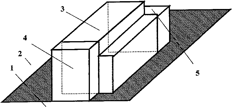
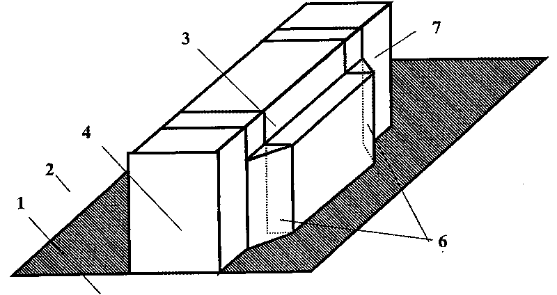
[0031] Such as figure 1 As shown, the present invention includes a substrate layer 1, a cover layer 2, and a core layer. The core layer is composed of an L-shaped conversion waveguide 3 connecting the rectangular input waveguide 4 and the rectangular output waveguide 5 whose size is different from the rectangular input waveguide.

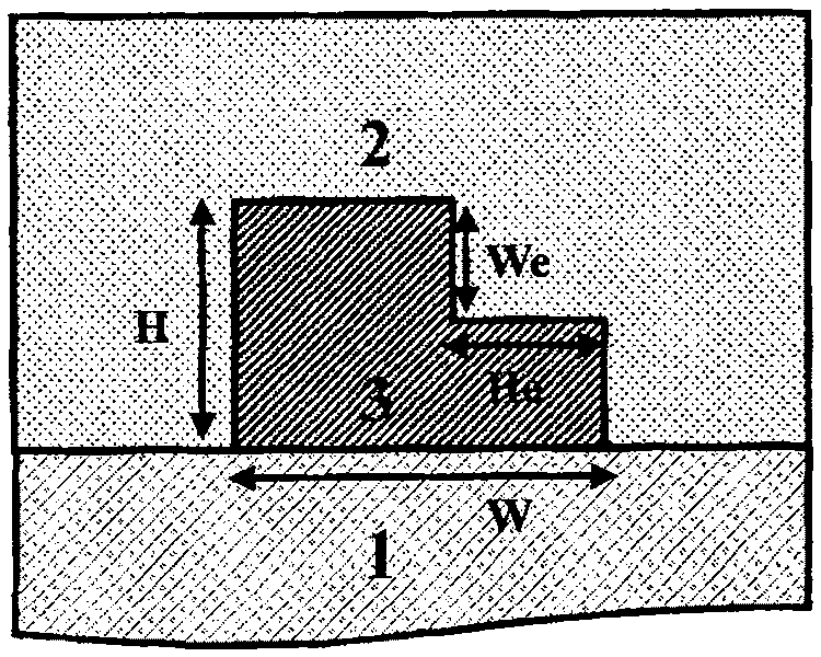
[0032] The height and width of the rectangular input waveguide 4 are respectively equal to the height of the L-shaped conversion waveguide 3 and the width of the left part of the cross section; the width and height of the rectangular output waveguide 5 are respectively equal to the width and the width of the L-shaped conversion waveguide 3 The width of the lower horizontal part of the section.

[0033] The refractive index of the cover layer 2 and the cross-sectional size of the core area of ​​the L-shaped conversion waveguide 3 make the mode polarization axis angle of the L-shaped conversion waveguide 3 45°.

[0034] The rectangular input waveguide 4 and...


PUM


Abstract

The invention discloses a waveguide type polarized mode converter, which is composed of a conventional dielectric waveguide which contains a substrate layer, a covering layer and a core layer; wherein, the core layer is formed by that the head and the tail of an L-shaped conversion waveguide are respectively connected with a rectangular input waveguide and a rectangular output waveguide which hasa different dimension with the input waveguide, and also can be formed by that the head and the tail of the L-shaped conversion waveguide are respectively connected with a rectangular input waveguideand a rectangular output waveguide which has the same dimension as the input waveguide through a conical transition waveguide. The converter can realize the polarized mode conversion between the rectangular waveguides with different dimensions or same dimensions. The input waveguides which are processes by the polarized conversion have wide dimensional variation range, and the single mode conditions are easy to satisfy. The converter has simple structure, the required fabrication technology is mature, the dimension is compact, the polarized conversion efficiency is high, the frequency range iswide and is easy to be integrated, and the converter can be widely applied to the optical integrated circuits which are operated in the single polarized mode.

Description

Technical field [0001] The present invention relates to a polarization mode converter, in particular to a waveguide type polarization mode converter. Background technique [0002] Because of the vector characteristics of light waves and the different boundary conditions of electric and magnetic fields at the boundary, there are two different polarization modes widely in the waveguide. The two modes in actual waveguides are often non-degenerate, have different propagation constants, and have different responses to external excitations, resulting in polarization mode dispersion, polarization loss dependence (correlation), and wavelength polarization dependence. Recently, there are two different research approaches to the polarization problem of waveguides. One is to optimize the device structure or compensation method to achieve polarization-independent characteristics; the other is to keep the device in a single polarization mode operating state (such as H.Fukuda). .et al, Opt. E...

Claims


Application Information

Patent Timeline
Patent Type & Authority Patents(China)
IPC IPC(8): G02B6/27
Inventor 周海峰江晓清王婉君孙一翎杨建义郝寅雷王明华
Owner ZHEJIANG UNIV
Why Eureka
Try Eureka