Optical fiber perimeter alarm method and device for implementing anti-polarization decay

An optical fiber perimeter, polarization fading technology, used in alarms, anti-theft alarms, optics, etc., can solve the problems of high operation and maintenance costs, affecting signal identification and judgment, high false alarm rate and false alarm rate, and reduce operation and maintenance costs. Maintenance cost, stable visibility, the effect of feedback control process simplification

Inactive Publication Date: 2008-12-10
BEIHANG UNIV
View PDF0 Cites 10 Cited by
  • Summary
  • Abstract
  • Description
  • Claims
  • Application Information

AI Technical Summary

Problems solved by technology

When the fiber is microbent, twisted, and the ambient temperature changes, the refractive index n corresponding to the two linear polarization modes transmitted by the fiber x and n y It also changes accordingly, which causes the polarization state of the output light of the signal arm or reference arm of the Mach-Zehnder interferometer to change, so that the two beams of light do not interfere completely during interference, resulting in the signal visibility after interference V It varies between 0 and 1; at the same time, the phase of the signal after interference will also be affected by the polarization state, light source and environment, which will cause the phase change of the output signal, resulting in position calculation errors, which will also have a great impact on the performance of the system
[0019] It can be seen that, according to the implementation scheme of the prior art, the amplitude of the output signal will be unstable due to the change of the visibility of the signal after the interference, so it cannot provide a signal with a stable amplitude for the subsequent judgment, which affects the signal. Identification and judgment make the system have a high rate of false alarms and false alarms, and the feedback control process of the existing system is more complicated, and the operation and maintenance costs are also higher

Method used


Image

  • Optical fiber perimeter alarm method and device for implementing anti-polarization decay
  • Optical fiber perimeter alarm method and device for implementing anti-polarization decay
  • Optical fiber perimeter alarm method and device for implementing anti-polarization decay

Examples


Embodiment Construction

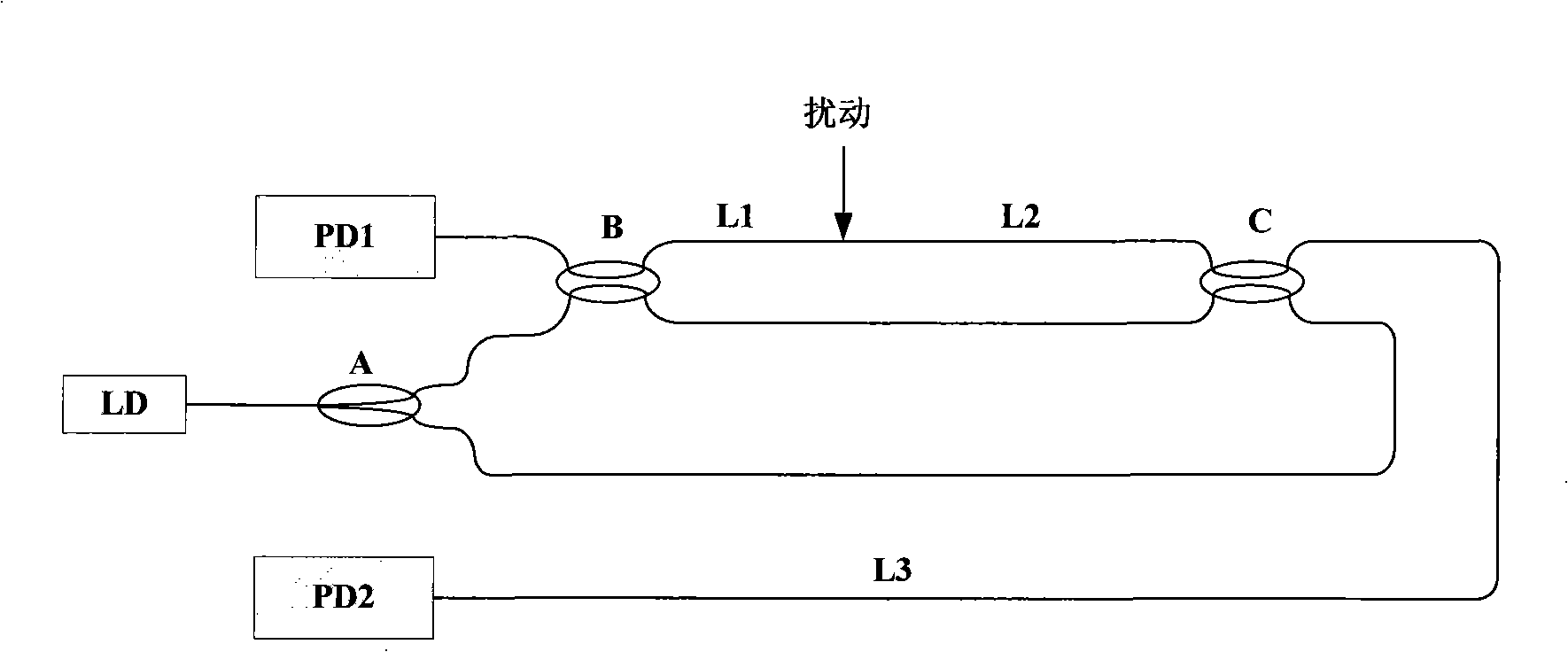
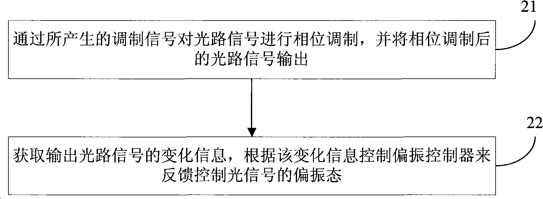
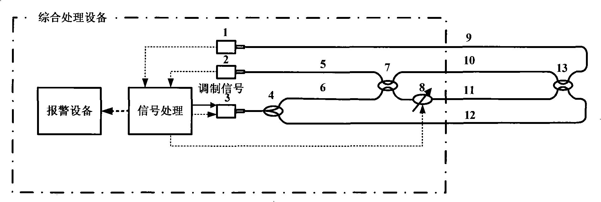
[0049]The embodiment of the present invention provides an optical fiber perimeter alarm method and device for realizing anti-polarization fading. First obtain the change information of the output optical path signal after phase modulation, and then control the polarization controller to feedback the polarization state of the optical signal according to the change information; the polarization controller here is set in a certain part of the Mach-Zehnder interferometer On one sensing fiber, the polarization controller is used to feed back and control the input polarization state of the Mach-Zehnder interferometer, thereby adjusting the output optical path signal of the path, providing a stable amplitude signal for signal identification, and finally realizing The highly stable and high-precision optical fiber perimeter alarm system improves the performance of the system; at the same time, the feedback control process of the system is more simplified, which further reduces the oper...


PUM


Abstract

The present invention provides an optical fiber perimeter warning method for realizing anti-polarization comedown and a device thereof. Concretely, a signal modulating module is used for modulating the phase of a light path signal and feeds back and controls the polarization state of the light path signal after the phase modulation; a polarization controller is arranged at one path sensing optical fiber of a Mach-Zehnder interferometer; the polarization controller is used for feeding back and controlling the input polarization state of a one path Mach-Zehnder interferometer and adjusting the output light path signal of the path, so the visibility of light path output can be stabilized by the technology of feeding back polarization control to provide the stable light path output signal for signal identification; at the same time, the feeding back and controlling process of a system is also simpler, thereby reducing the operating and maintaining cost of the system.

Description

technical field [0001] The invention relates to the field of alarm systems, in particular to an optical fiber perimeter alarm method and device for realizing anti-polarization fading. Background technique [0002] At present, the demand for security equipment has increased significantly, and the requirements for perimeter alarm systems are also getting higher and higher: long monitoring distance, low power consumption, high reliability, high stability, high alarm positioning accuracy, etc. In the current implementation scheme, the perimeter alarm system in the form of all-fiber based on the principle of distributed optical fiber stress sensor has high advantages and attractiveness. In the implementation scheme of the distributed optical fiber stress sensor, the two-way Mach-Zehnder interferometer scheme based on the principle of Mach-Zehnder interferometer using time difference positioning has the advantages of high sensitivity, real-time response and long-distance positioni...

Claims


Application Information

Patent Timeline
Patent Type & Authority Applications(China)
IPC IPC(8): G08B13/00G08B13/186G02F1/01G01L1/24
Inventor 李立京李琛林文台张春熹徐宏杰杨德伟邵洪峰罗光明李晨光王纪强
Owner BEIHANG UNIV
Why Eureka
Try Eureka