
Circuit arrangement for a transponder and method for operating a circuit arrangement

A transponder and circuit technology, applied in the field of transponders, to avoid parasitic loss and reduce power loss

Active Publication Date: 2008-12-10
NXP BV
View PDF1 Cites 5 Cited by
  • Summary
  • Abstract
  • Description
  • Claims
  • Application Information

AI Technical Summary

Problems solved by technology

At the same time, the maximum field strength that can be generated by the transponder base station is limited

Method used


Image

  • Circuit arrangement for a transponder and method for operating a circuit arrangement
  • Circuit arrangement for a transponder and method for operating a circuit arrangement
  • Circuit arrangement for a transponder and method for operating a circuit arrangement

Examples


Embodiment Construction

[0115] Hereinafter, the present invention will be described in more detail based on an embodiment example with reference to the accompanying drawings, in which the same or similar elements use the same or similar reference numerals.

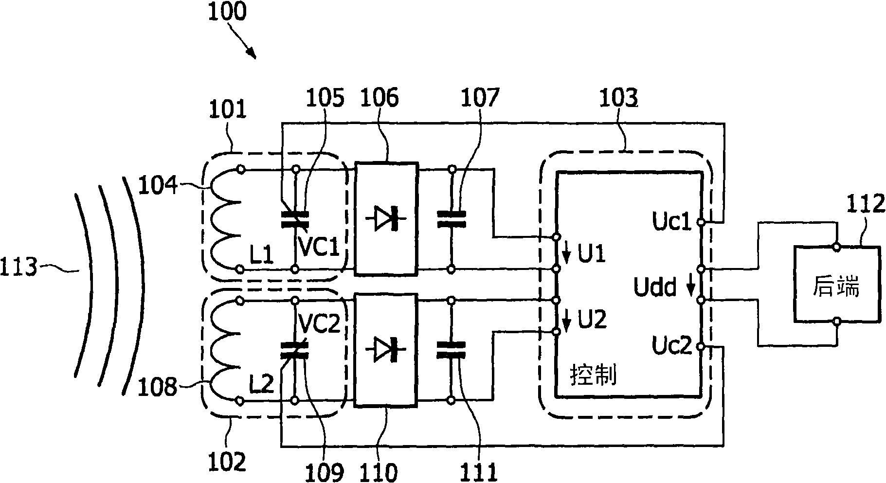
[0116] figure 1 An example of a circuit arrangement 100 for a transponder designed according to the invention is shown schematically in the form of a block diagram. In the figure, the front-end circuit is shown in detail and the back-end circuit is only illustrated as a module.

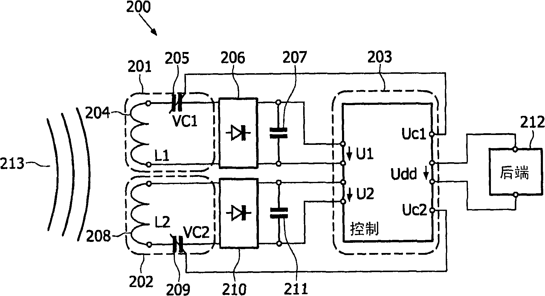
[0117] The circuit setup 100 includes a first resonator 101 , a second resonator 102 , a control circuit 103 and a backend circuit 112 . The first resonator 101 includes a first coil 104 and a first variable capacitor (varicap diode) 105 . The first resonator 101 is connected to a first rectifier circuit 106 which is connected to a first buffer capacitor 107 . The second resonator 102 includes a second coil 108 and a second variable capacitor (varicap diode) 109 . Th...


PUM


Abstract

A circuit arrangement (100) for a transponder comprises a control circuit (103) and an input circuit, wherein the input circuit comprises a first resonator (101), which comprises a first coil (104) and a first capacitor (105), and a second resonator (102), which comprises a second coil (108) and a second capacitor (109). The first capacitor and the second capacitor are designed as a first varactor and as a second varactor, respectively. Furthermore, the first resonator and the second resonator are designed in such a way that they can be used to provide a first output voltage and a second output voltage, respectively. Moreover, the control circuit (103) is designed in such a way that it can be used to control at least one of the varactors (105, 109) so that a resonant frequency of the corresponding resonator can essentially be set to a predefined transmission frequency such that the output voltage of the corresponding resonator of the input circuit can be increased.

Description

technical field [0001] The invention relates to a circuit arrangement and a method for operating a circuit arrangement, in particular a circuit arrangement for antenna matching, for the matching of an antenna to a circuit and for a data carrier which communicates wirelessly and is supplied with energy, a so-called reply Transponder. Background technique [0002] In the field of transponder technology, once transponders can be well established in the lower frequency range from about 100 kHz to tens of MHz, many current efforts are aimed at bringing the frequency range of hundreds of MHz to several GHz into the wider Applications. Statutory provisions and similar national or international decrees bind almost all applications to specific frequency bands, known as ISM bands. At the same time, the maximum field strength that can be generated by the transponder base station is limited. The ISM bands lie around center frequencies such as 434, 868, 915, 2450, 5800 and 24125 MHz. ...

Claims


Application Information

Patent Timeline
IPC IPC(8): G06K19/07
CPCG06K7/10178G06K19/0726G06K19/07749G06K19/07767G06K19/077G06K19/07H01Q1/24
Inventor 卡尔罗格马·里姆施奈德霍斯特·勒姆沃尔夫冈·托贝尔格特
Owner NXP BV
Learn More